Feed forward clock and data recovery unit

a forward clock and data recovery technology, applied in the direction of digital transmission, pulse automatic control, angle demodulation by phase difference detection, etc., can solve the problems of reducing the jitter budget, affecting the normal distorted and interfered received signals, and data signals at the receiver being subject to distortion

Inactive Publication Date: 2007-11-06
LANTIQ BET GMBH & CO KG
View PDF8 Cites 26 Cited by
  • Summary
  • Abstract
  • Description
  • Claims
  • Application Information

AI Technical Summary

Benefits of technology

The clock and data recovery unit described in this patent has several technical advantages. Firstly, it uses redundant data information for both phase synchronization and data recovery, making it very robust in noisy environments. Secondly, it is very robust with respect to variations or jitter of the sampling phase. Lastly, the same circuitry is used for two different functions at the same time, i.e. phase tracking and data recognition.

Problems solved by technology

The technical problem addressed in this patent is the inability of conventional clock and data recovery units to reliably recover data in a severely noisy environment with a high degree of interference and distortion. The small signal power of the received data signal is also leading to increased bit error rates. The patent proposes a new method that overcomes these limitations and achieves a higher bandwidth and better tracking of phase movements.

Method used


Image

  • Feed forward clock and data recovery unit
  • Feed forward clock and data recovery unit
  • Feed forward clock and data recovery unit

Examples


Embodiment Construction

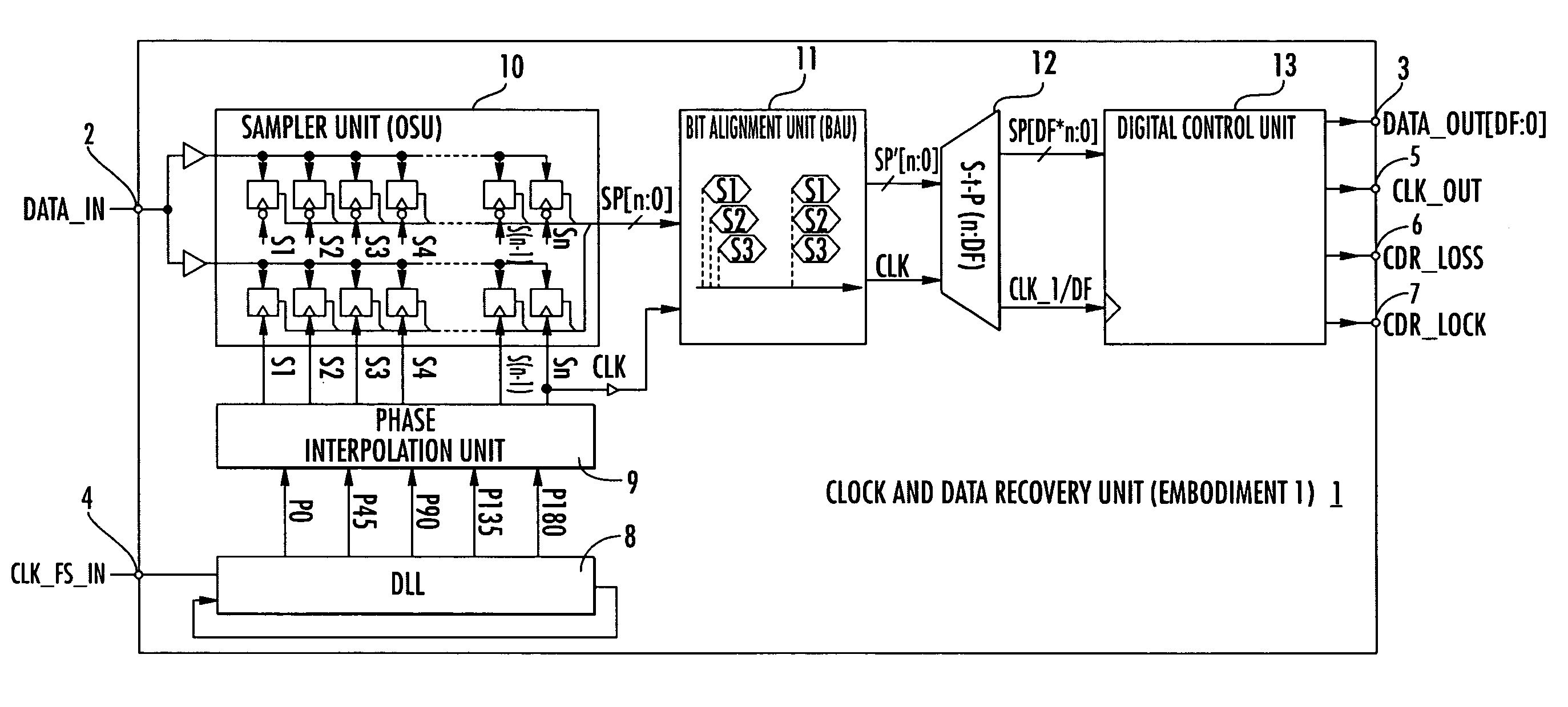
[0111]As can be seen from FIG. 4 the feed forward clock and data recovery unit 1 comprises a data input 2 for receiving the serial data bit stream over a data transmission channel. The recovered data streams are output by the clock and data recovery unit 1 via a data output terminal 3.

[0112]The feed forward clock and data recovery unit 1 further comprises a reference clock input terminal 4 for receiving a reference clock signal from a clock signal generator or a system clock signal. The recovered clock signal of the received serial bit stream is output by the feed forward clock and data recovery unit 1 via a clock output terminal 5. Further an output terminal 7 is provided for indicating that the feed forward clock and data recovery unit 1 has locked to the serial data bit stream. If the received serial data bit stream is interrupted or stopped this is indicated by the output terminal 6 of the clock and data recovery unit 1.

[0113]The feed forward clock and data recovery unit 1 accor...


PUM


Abstract

Disclosed is a feed forward clock and data recovery unit for recovering a received serial data bit stream having a feed forward phase tracking unit for tracking of a sampling time to the center of a unit interval of the received data bit stream. The feed forward phase tracking unit can include a sampling phase generation unit, an oversampling unit, a serial-to-parallel-conversion unit, a binary phase detection unit, a loop filter, a finite state machine, a binary rotator, and a data recognition unit for recovery of the received data stream which includes a number of parallel data recognition FIR-Filters. Further, each data recognition FIR-Filter can include a weighting unit for weighting data samples of the deserialized data stream, a summing unit for summing up the weighted data samples, and a comparator unit for comparing the summed up data samples with a threshold value.

Description


Claims


Application Information

Patent Timeline
Owner LANTIQ BET GMBH & CO KG
Why Eureka
Try Eureka