Automatically operated bed

Active Publication Date: 2007-11-13
RUOEY LUNG ENTERPRISE
View PDF4 Cites 30 Cited by
  • Summary
  • Abstract
  • Description
  • Claims
  • Application Information

AI Technical Summary

Benefits of technology

[0008]The primary objective of the present invention is to provide an automatically operated bed, wherein the first frame and the second frame are lifted or lowered by operation of the first drive cylinder and the second drive cylinder, so that the bed has a simplified construction, thereby decreasing the costs of fabrication.
[0009]Another objective of the present invention is to provide an automatically operated bed, wherein the bed has a simplified construction, thereby

Problems solved by technology

However, the drive mechanism 66 has a complicated construction, thereby increasing the costs of fabrication.
In addition, the drive mechanism 66 has a complicated construction, thereby causing inconvenience in maintenance of the

Method used


Image

  • Automatically operated bed
  • Automatically operated bed
  • Automatically operated bed

Examples


Embodiment Construction

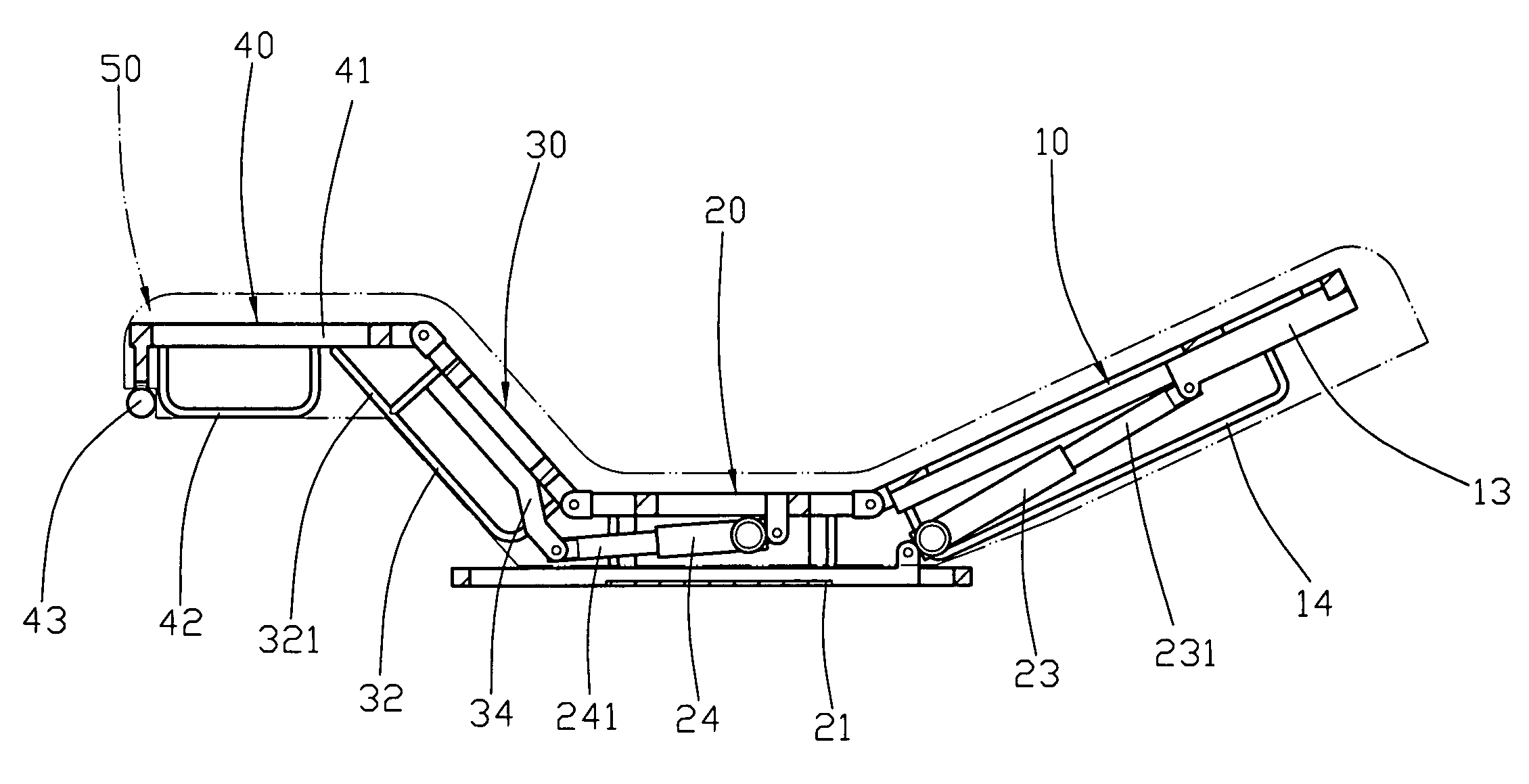
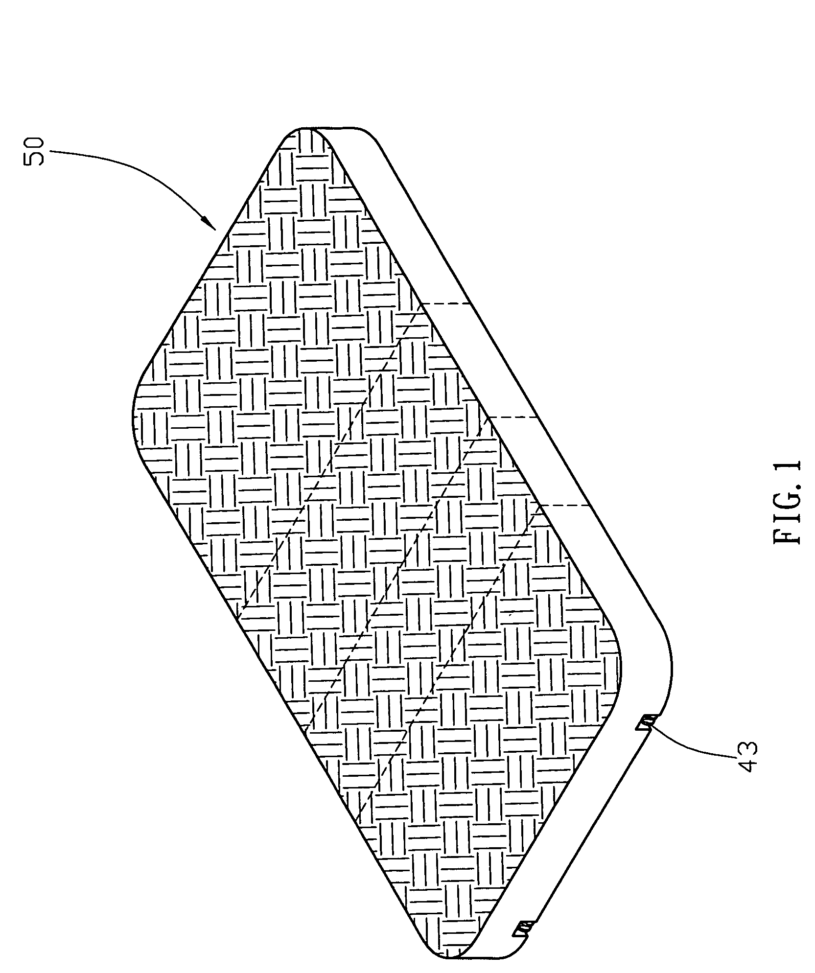
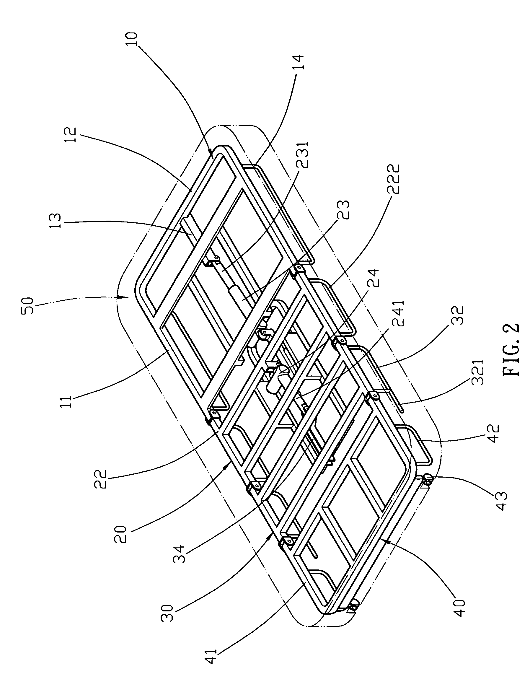
[0026]Referring to the drawings and initially to FIGS. 1-4, an automatically operated bed, such as a motorized bed, in accordance with the preferred embodiment of the present invention comprises a support frame 20, a first frame 10 having a first portion pivotally mounted on a first portion of the support frame 20, a first drive cylinder 23 having a first portion pivotally mounted on the support frame 20 and a second portion provided with a retractable first drive rod 231 pivotally mounted on a second portion of the first frame 10, a second frame 30 having a first portion pivotally mounted on a second portion of the support frame 20, a second drive cylinder 24 having a first portion pivotally mounted on the support frame 20 and a second portion provided with a retractable second drive rod 241 pivotally mounted on the second frame 30, an auxiliary frame 40 having a first portion pivotally mounted on a second portion of the second frame 30 and a second portion provided with two roller...


PUM


Abstract

An automatically operated bed includes a support frame, a first frame, a first drive cylinder, a second frame, a second drive cylinder, an auxiliary frame, and a cushion. Thus, the first frame and the second frame are lifted or lowered by operation of the first drive cylinder and the second drive cylinder, so that the bed has a simplified construction, thereby decreasing the costs of fabrication. In addition, the auxiliary frame is disposed at a horizontal state by support of the push bar of the second frame until the auxiliary frame so that a user's lower leg is supported by the auxiliary frame in comfortable manner to prevent the user's leg from being bent excessively, thereby providing a comfortable sensation to the user.

Description

BACKGROUND OF THE INVENTION[0001]1. Field of the Invention[0002]The present invention relates to a bed and, more particularly, to an automatically operated bed.[0003]2. Description of the Related Art[0004]A conventional automatically operated bed 60 in accordance with the prior art shown in FIGS. 11-13 comprises a support frame 63, a front frame 61 mounted on a front portion of the support frame 61, a front cushion 64 mounted on the front frame 61, a rear frame 62 mounted on a second portion of the support frame 61, a rear cushion 65 mounted on the rear frame 62, and a drive mechanism 66 mounted on the front frame 61 for moving the front cushion 64 and the rear cushion 65. The drive mechanism 66 includes a drive motor661 to rotate a drive shaft 662 which drives a movable tube 663 to move forward and backward by rotation of the drive shaft 662, an elastic wire 664 having a first end secured to a distal end of the movable tube 663 and a second end secured to a hook 651 of the rear cus...

Claims


Application Information

Patent Timeline
IPC IPC(8): A61G7/015
CPCA47C20/041A47C20/08A61G7/015
Inventor SHIH, LUNG-TAN
Owner RUOEY LUNG ENTERPRISE
Why Eureka
Try Eureka