Tubular handle for a manually guided implement

a technology of hand-held implements and tubular handles, which is applied in the direction of chainsaws, manufacturing tools, portable power-driven tools, etc., can solve the problems of affecting the bearing strength, and affecting the flow of material

Active Publication Date: 2007-11-13
ANDREAS STIHL AG & CO KG
View PDF24 Cites 8 Cited by
  • Summary
  • Abstract
  • Description
  • Claims
  • Application Information

AI Technical Summary

Benefits of technology

[0019]The present application proposes a tubular handle, the circular cross section of which, in the region of the mounting portion, is flattened to form an at least approximately planar abutment portion, whereby beyond the abutment portion a circular cross-sectional portion is retained. In this connection, the flattened abutment portion is provided for the securement of the tubular handle to the implement. The flattening of the cross section on one side leads to a flat or laminar engagement of the tubular handle against the implement, with such abutment providing a good transfer of forces that occur. Only a slight deformation of the cross section is necessary, thereby reducing the stress on the material during the deformation process. The circular cross-sectional portion that is retained leads, in conjunction with the flattened abutment portion, to a relatively high surface moment of inertia about all main axes, as a consequence of which a high rigidity and a high bearing strength result in all directions of stress or loading. Due to the securement of the tubular handle to the implement merely via the flat abutment surface, the circular cross-sectional portion that is retained is free of screwing or fastening forces. A cross-sectional deformation that reduces the bearing strength under operating loads is avoided.
[0020]Pursuant to an advantageous further development, the flattened abutment portion merges via a rounded section with the adjoining cross-sectional portion. An excessive material deformation is avoided in this region. The rounded portion contributes to the stiffening or reinforcement of the cross section.

Problems solved by technology

During operation of the power chain saw, considerable holding forces can occur at the tubular handle.
The high degree of deformation of the material of the tube leads, during the manufacturing process, to a considerable flow of material.
In the transition region between the deformed and nondeformed cross section of the tube, cracks or splits can result that adversely affect the bearing strength.

Method used


Image

  • Tubular handle for a manually guided implement
  • Tubular handle for a manually guided implement
  • Tubular handle for a manually guided implement

Examples


Embodiment Construction

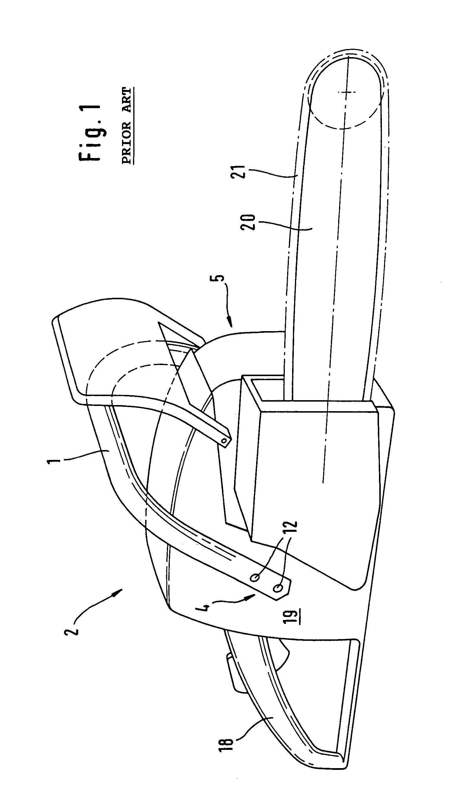
[0032]Referring now to the drawings in detail, FIG. 1, in a perspective schematic illustration, shows an implement 2, by way of example a power chain saw. The implement 2 is provided with a motor portion 19, of the rear side of which is connected a rear handle 18. The motor portion 19 is spanned above and to the side by a tubular handle 1, whereby the implement 2 can be held and guided with one hand on the rear handle 18 and the other hand on the tubular handle 1. On that end that is opposite the rear handle 18, the power chain saw is provided with a guide bar 20 about which circulates a cutting chain 21. When the guide bar 20 with the cutting chain 21 penetrates into material that is to be cut, correspondingly high manual forces are to applied, in particular via the tubular handle 1. Reaction forces from the cutting process can increase the forces at the tubular handle 1.

[0033]The tubular handle 1 shown in FIG. 1 is embodied pursuant to the state of the art, and is screwed to the m...


PUM


Abstract

A tubular handle for a manually guided implement, especially a power chain saw or the like, is provided. The handle has an essentially circular cross-section and at least one mounting portion for fixing the handle to the implement. In the area of the mounting portion, the circular cross-section is flattened to form an at least approximately planar abutment portion, beyond which a circular cross-sectional portion is retained. The abutment portion is provided for fixing the tubular handle to the implement.

Description

BACKGROUND OF THE INVENTION [0001]The present invention relates to a tubular handle for a manually guided implement, especially a power chain saw or the like, with an essentially circular cross section and with at least one mounting portion for fixing the tubular handle to the implement.[0002]Manually guided implements, such as chain saws or the like, are provided with a tubular handle that is mounted on the implement for carrying and guiding the latter. During operation, for example of a power chain saw, the latter is guided with two hands, with one hand grasping a rear handle that is secured to the housing, and with the front tubular handle of the power chain saw being held and guided by the other hand. During operation of the power chain saw, considerable holding forces can occur at the tubular handle.[0003]For the securement of the tubular handle to the implement, the tubular handle is provided with at least one mounting portion, whereby the tubular handle can, for example, be s...

Claims


Application Information

Patent Timeline
Patent Type & Authority Patents(United States)
IPC IPC(8): B25G3/32B25F5/00B27B17/00
CPCB27B17/0008B27B17/0033Y10T16/469Y10T16/466Y10T16/499Y10S16/41
Inventor GUIP, ANDREASMENZEL, JOHANNESSCHLESSMANN, HELMUTKEMMLER, RALF-RAINERDECKER, HARALDWOLF, GUNTER
Owner ANDREAS STIHL AG & CO KG
Why Eureka
Try Eureka