Hanging shoe rack with improved structural features

a shoe rack and structural feature technology, applied in the field of shoe racks, can solve the problems of adding to the cost, adding material cost, adding molding cost, etc., and achieve the effect of reducing the mold cycle time, saving costs and less material

Inactive Publication Date: 2007-11-13
LYNK I NC
View PDF8 Cites 7 Cited by
  • Summary
  • Abstract
  • Description
  • Claims
  • Application Information

AI Technical Summary

Benefits of technology

[0008]The present invention is directed to a shoe rack that is of the general type shown in U.S. Pat. No. 5,695,073 but is improved in a number of respects. As a result of these improvements, the quantity of material (typically molded plastic) can be reduced by up to one pound which creates important cost savings and advantages in shipping and handling of the product. Also, significant cost savings are achieved because the mold cycle time is reduced due to the thinner parts and the part design which better accommodates free flow of plastic throughout the mold cavity during the molding operation. An improved hanger bracket is also provided which requires less material and has improved structural features as well.
[0009]In accordance with one aspect of the invention, the arms that support the shoes are constructed with lower flanges that are significantly narrow than the upper flanges which are more visually prominent. By tapering the arm members in this manner, the material requirements are reduced. At the same time, the arm members appear to be large and strong because only the relatively large top flanges are readily noticeable.
[0010]According to another aspect of the invention, the hanger bars at the top ends of the frame sides have connections that are made in smooth and gradual curves rather than abruptly at right angles. As a result of this curved transition, adequate strength is provided without creating areas of stress concentration that require a gusset reinforcement. The elimination of gusset plates adds to the reduction in the material requirements and enhances the aesthetics of the product. The thinner hanger bars reduce the costs in that less material is required and the mold cycle time is reduced.
[0012]A further aspect of the invention involves an improved connection between the hanger bars and the brackets that hang the shoe rack on the door. The ends of the bars have L-shaped tongues on which tabs are provided to strengthen the downwardly projecting legs of the tongues. Additionally, when the legs are received in slots on the hanger brackets, the tabs fit closely through notches in the brackets in order to strengthen and stabilize the connections and resist side to side sway of the shoe rack on the brackets.

Problems solved by technology

This adds to the cost in two ways—the material cost itself and the added molding cost resulting from the increased mold cycle cost due to the relatively thick parts that must be molded.
Consequently, gusset plates are required at these connections in order to structurally reinforce what otherwise would be a weak area subject to stress concentration and possible failure.
As a result, these connections between the frame sections can create problems from a strength standpoint unless the parts are relatively large.
However, this increases the amount of material that is required and the material costs are increased accordingly, as is the cost due to the increased mold cycle time that is required to make the part.
Again, this increases the material costs.
It is also possible for the shoe rack frame to sway side to side on the brackets when the door is swung open or closed, and this can cause the shoes to become displaced and create other problems.

Method used


Image

  • Hanging shoe rack with improved structural features
  • Hanging shoe rack with improved structural features
  • Hanging shoe rack with improved structural features

Examples


Embodiment Construction

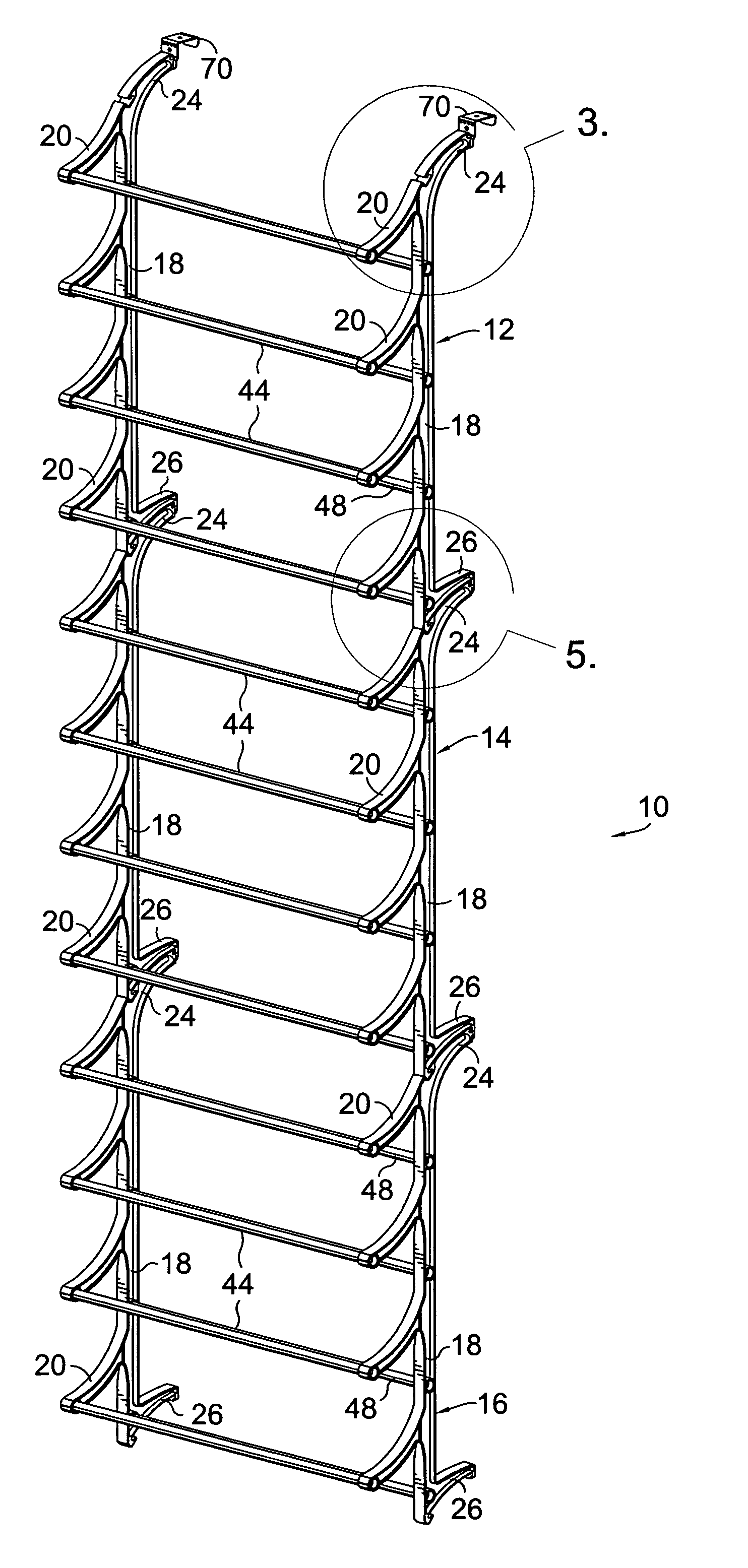
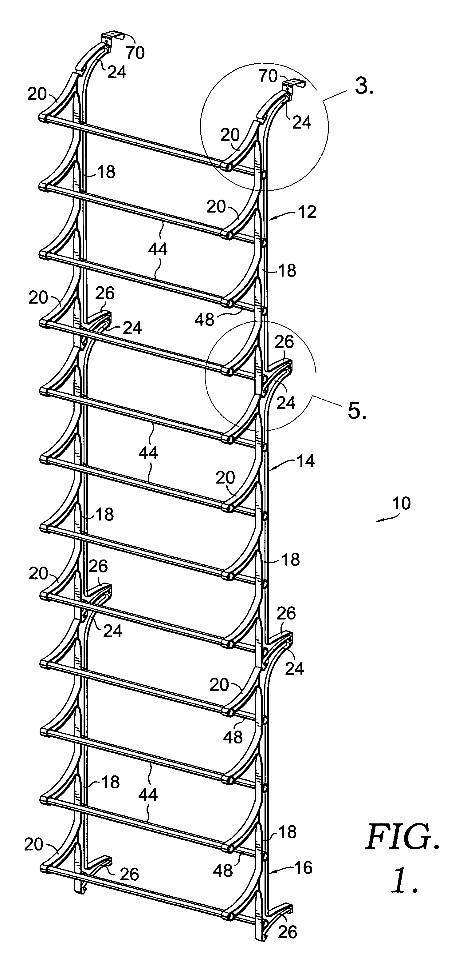
[0025]Referring now to the drawings in more detail and initially to FIG. 1 in particular, numeral 10 generally designates a hanging shoe rack constructed according to a preferred embodiment of the present invention. A shoe rack 10 include an upper section 12, an intermediate section 14 immediately below the upper section 12, and a bottom section 16 located immediately below the intermediate section 14. It should be understood that three sections are shown only by way of example and that the shoe rack can be constructed using a different number of sections.

[0026]Each of the sections 12, 14 and 16 may have the same construction and includes a frame having opposite parallel sides 18 that may be identical to one another. Each frame side 18 is provided with a plurality of spaced apart arms 20 which extend in a slightly curved configuration outwardly from the frame side or in a direction away from a vertical surface on which the shoe rack 10 is mounted (such as on a wall or other surface ...


PUM


Abstract

A hanging shoe rack for a closet door or other vertical surface. Frame sections have opposite sides provided with support arms that taper from top to bottom for reduced material requirements. The sections are connected by bars and feet having L-shaped tongues fitting in L-shaped slots with long curved surfaces in contact for enhanced strength. The bars that receive hanger brackets have strong curved connections with the frame sides. The tongues on the bars that hook to the brackets are reinforced by tabs that fit closely in notches in the brackets to resist side to side sway.

Description

CROSS-REFERENCE TO RELATED APPLICATIONS[0001]Not applicable.STATEMENT REGARDING FEDERALLY SPONSORED RESEARCH OR DEVELOPMENT[0002]Not applicable.TECHNICAL FIELD[0003]The present invention relates generally to hanging shoe racks and more particularly to shoe racks that can be hung on doors and other upright surfaces.BACKGROUND OF THE INVENTION[0004]Shoe racks that hang on closet doors have achieved considerable popularity, in large part because they allow shoes to be conveniently stored in a space that is otherwise not normally used. It is important from a cost standpoint to minimize the amount of material that is required to manufacture this type of shoe rack. At the same time, the shoe rack must be constructed with sufficient strength to withstand the forces that are applied to it in normal use, such as when the shoe rack is heavily loaded and the door is swung open or closed. Further, the appeal of the product is enhanced by maintaining an attractive appearance and particularly an ...

Claims


Application Information

Patent Timeline
Patent Type & Authority Patents(United States)
IPC IPC(8): A47F7/08
CPCA47B61/04
Inventor KLEIN, RICHARD B.SCOTT, JOHN W.SERSLEV, CHRIS
Owner LYNK I NC
Why Eureka
Try Eureka