Cable holder

a cable holder and cable technology, applied in the field of cable holder, can solve the problems of limited access to the inner hanger, insertion of the cable holder, and increase the number of transmission lines

Active Publication Date: 2007-11-13
PIROD
View PDF18 Cites 51 Cited by
  • Summary
  • Abstract
  • Description
  • Claims
  • Application Information

AI Technical Summary

Benefits of technology

[0009]In accordance with one aspect of the invention, to facilitate access by the worker to an inner hanger couplable to a support, inner and outer hangers are displaceable relative to one another about an axis offset from a central symmetry axis. As opposed to the structure shown in FIGS. 1 and 2, displacement of the hangers about the off-center axis leads to a position in which the inner hanger can be conveniently gripped and squeezed by the worker. As a result, displacing the outer hanger relative to the inner one in accordance with the invention creates a sufficient space allowing the worker to manually attach the inner hanger to a support.
[0010]In accordance with another aspect of the invention, the outer hanger is configured to positively lock a cable in the hanger. A locking assembly is characterized by its simplicity and is configured to allow reliable accommodation of differently sized cables.
[0013]Still a further object of the invention is to provide a reliable securement of cables to the inventive cable holder.

Problems solved by technology

The advent of electronic equipment has caused a few problems related to coupling of a hugely increased number of transmission lines along antenna towers due to a limited space capable of accommodating these lines.
Insertion of the cable holder may pose several problems.
For example, if the cable holder, as shown in FIGS. 1 and 2, is assembled before its attachment to the support 118, the access to the inner hanger may be limited because the outer hanger blocks the inner one, which is, thus, difficult to reach manually.
Thus, this structure necessitates the use of instruments, which are a) inconvenient, since the direct access to the inner hanger is still blocked by the outer hanger, and b) undesirable, because having additional instruments on a tall tower imposes an additional physical and logistical hardship on the serviceman.
If, however, the cable holder of FIGS. 1 and 2 is deployed by initially attaching only the inner hanger with a respective cable to the support 118, further installation of the outer hanger in response to the increased demands for additional cables may be associated with difficulties caused by climatic conditions.
As a consequence, low temperatures and strong winds may critically complicate the attachment of the outer hanger to the inner one.
Also, gradual installation of subsequent outer hangers may be associated with still another problem stemming from variations of the size of the opening 116 leading to unreliable securing the hangers to one another and to the support 118.
Overall, the above-discussed problems may detrimentally affect the reliability of the installation as well as the safety of the worker.
Yet, the inherent elasticity of the arms of the hanger may not be sufficient to prevent displacement of the cables along the tower for a variety of reasons.
Even those hanger designs that have mechanisms for penetrating or biting into the cable jacket may not prevent longitudinal movement of the cable because the frictional coefficient between the metal hanger and the plastic cable jacket is very low.
In addition, the cable jacket can “cold flow” which reduces the holding force of the cable hanger over time, resulting in cable slippage.

Method used


Image

  • Cable holder
  • Cable holder
  • Cable holder

Examples


Embodiment Construction

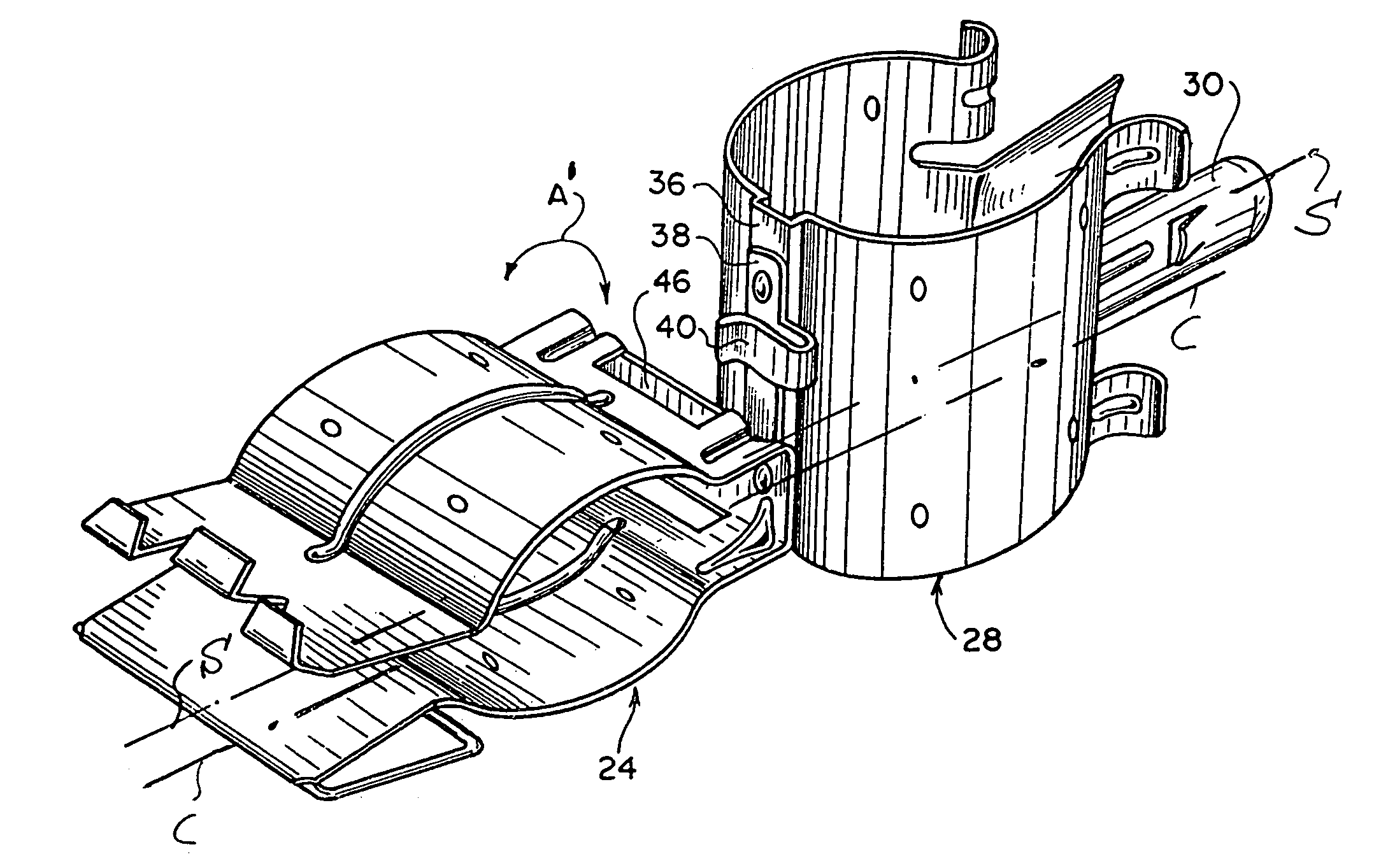
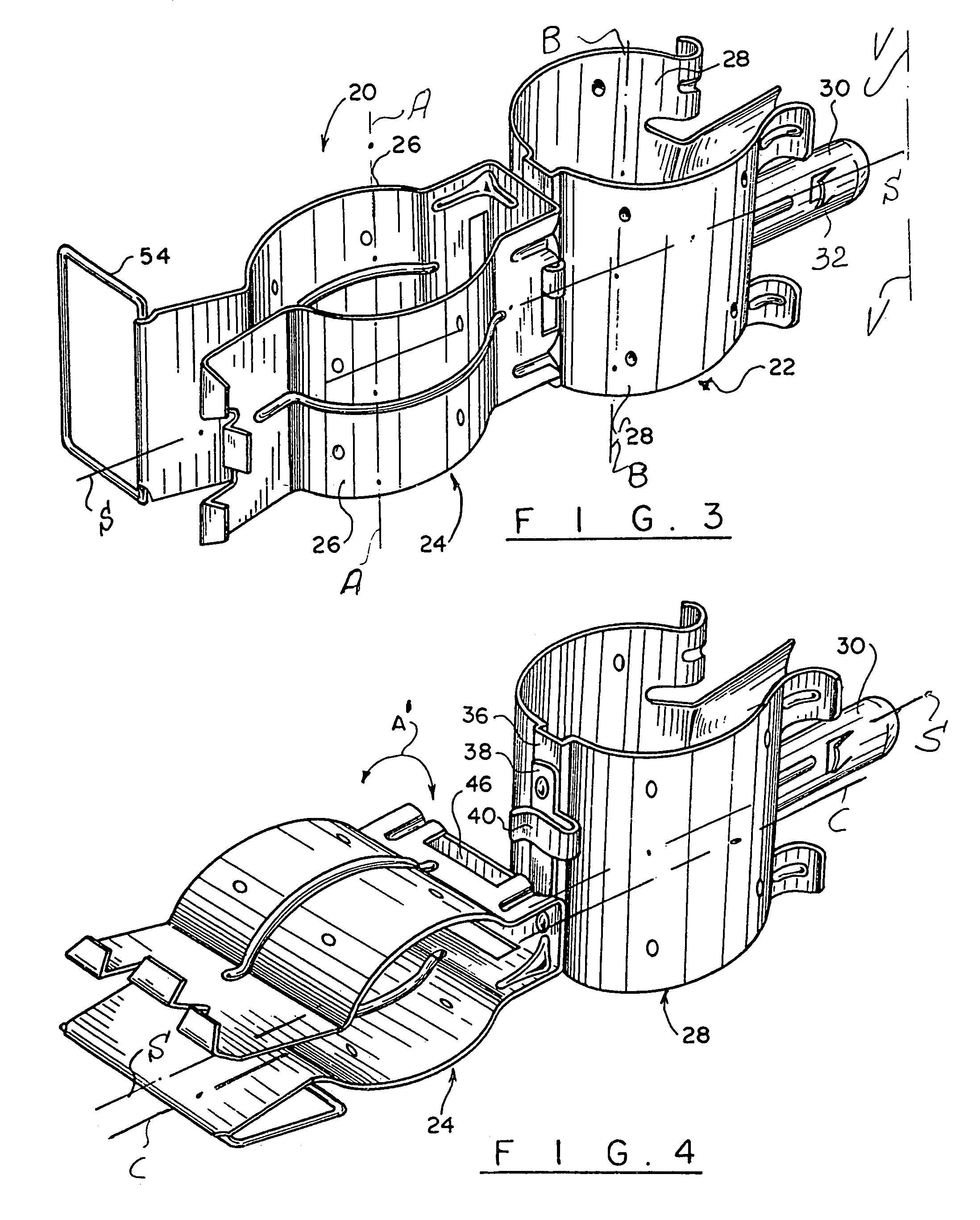
[0023]Referring to FIGS. 3-4, the inventive cable holder 20 has at least one pair of coupled inner 22 and outer 24 hangers displaceable relative to one another along a direction “A′” between deployed and installation positions as shown in FIGS. 3 and 4, respectively. In accordance with one inventive embodiment, the hangers 22, 24 rotate relative to one another about an axis C-C (FIG. 4), which is offset from an axis of symmetry S-S (FIG. 4) common to both hangers in the deployed position of FIG. 3. Accordingly, in the deployed position, the axis of symmetry S-S of both hangers 22, 24 extends substantially perpendicular to a longitudinal axis V-V of an antenna tower (not shown), which complicates access to a body 28 of the inner hanger 22 by a serviceman. To facilitate this access, the outer hanger 24 is designed to move so that the body 28 is conveniently exposed to the serviceman. The serviceman then applies a compressing force to the body 28, brings the fingers 30 together to inse...


PUM


Abstract

A cable holder for securing multiple elongated objects to a support has a plurality of inner and outer hangers fixedly attached to one another and each configured to receive a respective one of the multiple elongated objects. The inner and outer hangers are displaceable relative to one another so that the outer hanger does not block the inner hanger during attachment of the latter to a support.

Description

FIELD OF THE INVENTION[0001]The invention relates to a cable holder configured to support one or more cables.BACKGROUND OF THE INVENTION[0002]The use of transmission line or cable hangers, or clamps, configured to attach a transmission line or cable to a support, such as an antenna tower, have been known for many years. The advent of electronic equipment has caused a few problems related to coupling of a hugely increased number of transmission lines along antenna towers due to a limited space capable of accommodating these lines. Typically, since installation of cables is associated with safety considerations as well as with the time and expense involved with installing these lines, it is highly desirable to minimize both the amount of time and the complexity of the work required for coupling cables to support structures. To address these issues, various structures of cable hangers, designed to rapidly attach cables to support structures, have been recently developed.[0003]A typical...

Claims


Application Information

Patent Timeline
Patent Type & Authority Patents(United States)
IPC IPC(8): F16L3/00F16L3/22
CPCH02G3/30F16L3/222
Inventor CATAPANO, JOSEPH P.
Owner PIROD
Why Eureka
Try Eureka