Chair and support mechanism unit thereof

a technology of support mechanism and chair, which is applied in the field of chair (, can solve the problems of inability to provide a comfortable rocking motion, limited length of compression coil spring, and great load on the compression coil spring, and achieves simple and quick action, easy adjustment of initial elastic force, and improved durability.

Inactive Publication Date: 2007-11-13
ITOKI CORP
View PDF15 Cites 54 Cited by
  • Summary
  • Abstract
  • Description
  • Claims
  • Application Information

AI Technical Summary

Benefits of technology

[0020]In the present invention, since a site further behind the tilt supporting point of the back support unit is supported by a spring means, a load point which acts on the spring means is made distant from the tilt supporting point of the back support unit, thereby making it possible to reduce a load acting on the spring means, as compared with a conventional one which deforms a spring means by leverage.
[0035]Since the base, the back support unit and the spring unit are formed integrally in the support mechanism unit of the present invention, it is advantageous in conducting an efficient assembly of the chair. The advantage is particularly brought about when chairs are assembled by a knock-down method.

Problems solved by technology

In the chair disclosed by the above two publications and many other chairs, since a pressing force is allowed to act upon a compression coil spring at a site further forward than a tilt supporting point (turnable supporting point) of a back support unit, the compression coil spring undergoes a great load due to the leverage, while at the same time, the compression coil spring is restricted in length due to a limited space inside the base.
However, where the spring is kept in a certain posture as disclosed in the publications, a problem occurs when either a backrest abruptly tilts backward for a very short time when a seated person reclines against the backrest, or only a slight backward tilt does not produce a backward tilt due to an abruptly increased repulsive force of a spring, thereby making it impossible to provide a comfortable rocking motion.
However, a greater initial elastic force of the compression coil spring only results in a difficulty in backward tilt, and no comfort is, therefore, expected when a greater initial elastic force is imparted to the compression coil spring.
However, there has been a problem in that a conventional spring is restricted in length and a backward tilt angle of the backrest is restricted accordingly, making it difficult to increase a backward tilt angle of the backrest.
In addition, another problem occurs where a handle for adjusting an initial elastic force of a spring is arranged on a lower surface of a base, a person has to operate the handle in a bent posture, therefore, making the adjusting operation more troublesome.
However, there is one problem that workability is not always good in assembling of chairs.
It may take more time and labor to assemble the chair, because the attachment of the outer shell to the back support unit and the attachment of the inner shell to the outer shell must be performed.
It is, therefore, required to reduce the number of components as much as possible, for which a conventional backrest structure will not satisfy the requirement.
There is also a problem related to the conventional three-layer structured backrest that only an outer shell does not function as a backrest and always needs a cushion-equipped inner shell, which makes it difficult to simplify the structure.
Therefore, a person is not allowed to recline against the outer shell, thus making it impossible to simplify the structure of the backrest.

Method used


Image

  • Chair and support mechanism unit thereof
  • Chair and support mechanism unit thereof
  • Chair and support mechanism unit thereof

Examples


first embodiment

(1) Outline of a First Embodiment

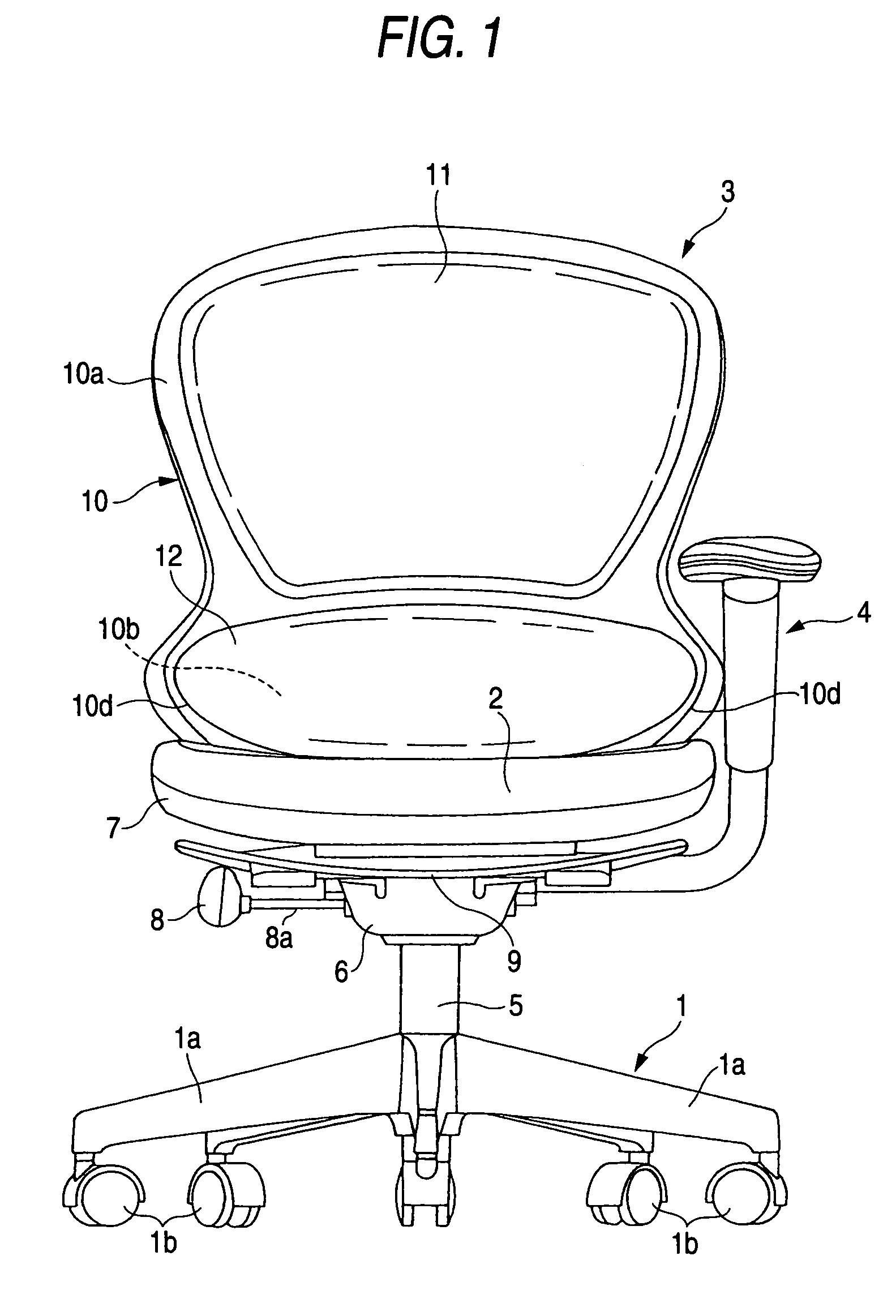
[0056]First, an explanation will be made for the outline of the first embodiment by referring to FIG. 1 through FIG. 5. The chair is provided with a leg 1, a seat 2, a backrest 3 and an armrest device 4 (the armrest device 4 is available in a pair of right and left armrest devices but only one of them is illustrated in the figure). The leg 1 is provided with a leg pillar 5 including a gas cylinder and a plurality of branch legs 1a (5 branch legs) extending in a radial manner. A caster 1b is provided at each front end of the branch legs 1a.

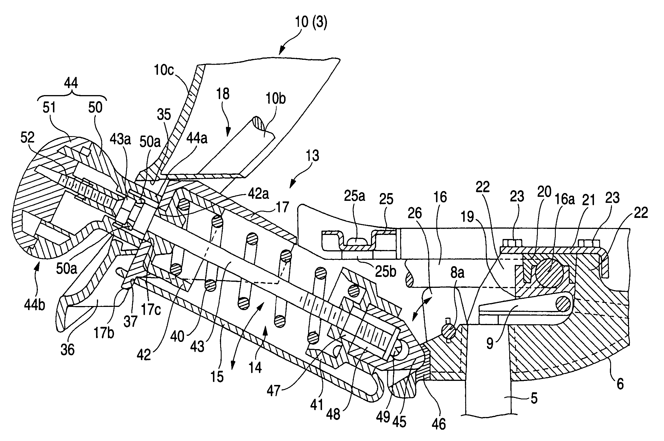
[0057]A base 6 opened upward is attached at an upper end of the leg pillar 5, a seat-receiving outer shell 7 is attached at an upper surface of the base 6, and the seat 2 is attached to the seat-receiving outer shell 7. A lock operation lever 8 for switching a state where the backrest 3 is allowed to tilt backward to a state where it is not allowed to tilt backward is exposed from the left side surface of the base ...

second embodiment

(5) Second Embodiment

[0106]FIG. 12 and FIG. 13 shows a second embodiment. In the second embodiment, a catch portion 33 of a main member 10 in a backrest 3 is opened forward. Further, although a whole picture is not given in the drawing, the second embodiment is provided with a back support unit 13 similar to that provided in the first embodiment.

[0107]Then, in the embodiment, on attaching the backrest 3 to the back support unit 13, a main member 10 is fitted completely into a pillar portion 18c of a second frame 18 by utilizing elastic deformation of the second frame 18 of the back support unit 13 and the main member 10, and then an horizontal axis portion 18a of the second frame 18, the main member 10, and the catch portion 33 are fitted together.

(6) Other

[0108]The present invention may be available in various modes, in addition to the above-described embodiments. For example, a configuration of the back receiving unit and that of the base may be modified in any way according to th...


PUM


Abstract

A chair is provided with a base 6 fixed at an upper end of a leg pillar 5, a back support unit 13 attached to the base 6 so as to tilt backward, a backrest 3 attached to the back support unit 13, and a spring unit 14 supporting the backward tilt of the back support unit 13. The spring unit 14 is to expand and contract in a back and forth direction when viewed from above and arranged further behind than a tilt supporting point 16a of the back support unit 13. The back support unit 13, the spring unit 14, and the base 6 constitute a kind of link mechanism and the spring unit 14 will expand and contract mainly at the front end, while tilting backward.

Description

BACKGROUND OF THE INVENTION[0001]1. Field of the Invention[0002]The present invention relates to a chair (rocking chair) provided with a backrest which tilts backward and a support mechanism unit which is used thereof.[0003]2. Description of the Related Art[0004]In a rocking chair, whose backrest tilts backward, a spring means is used to support the backward tilt of the backrest. The spring means includes a compression coil spring, blade spring, torsion bar, rubber, gas cylinder (or gas spring) and the like, and in general, a compression coil spring is commonly used. The compression coil spring is in most cases arranged in a box-shaped base opened upward in a posture extending approximately in a back and forth direction, when viewed from above.[0005]Further, the coil spring is supported by front and rear spring bearings, and a space between these front and rear spring bearings adjusts an initial elastic force (hardness) of the coil spring. The initial elastic force of the coil sprin...

Claims


Application Information

Patent Timeline
Patent Type & Authority Patents(United States)
IPC IPC(8): A47C1/024
CPCA47C3/026A47C7/443A47C7/441
Inventor TAKEUCHI, HIROSHIOGATA, HIROTO
Owner ITOKI CORP
Why Eureka
Try Eureka