
Composite prosthesis

a prosthesis and composite technology, applied in the field of prosthesis, to achieve the effect of saving inventory costs

Active Publication Date: 2007-11-13
COOK MEDICAL TECH LLC +1
View PDF18 Cites 181 Cited by
  • Summary
  • Abstract
  • Description
  • Claims
  • Application Information

AI Technical Summary

Benefits of technology

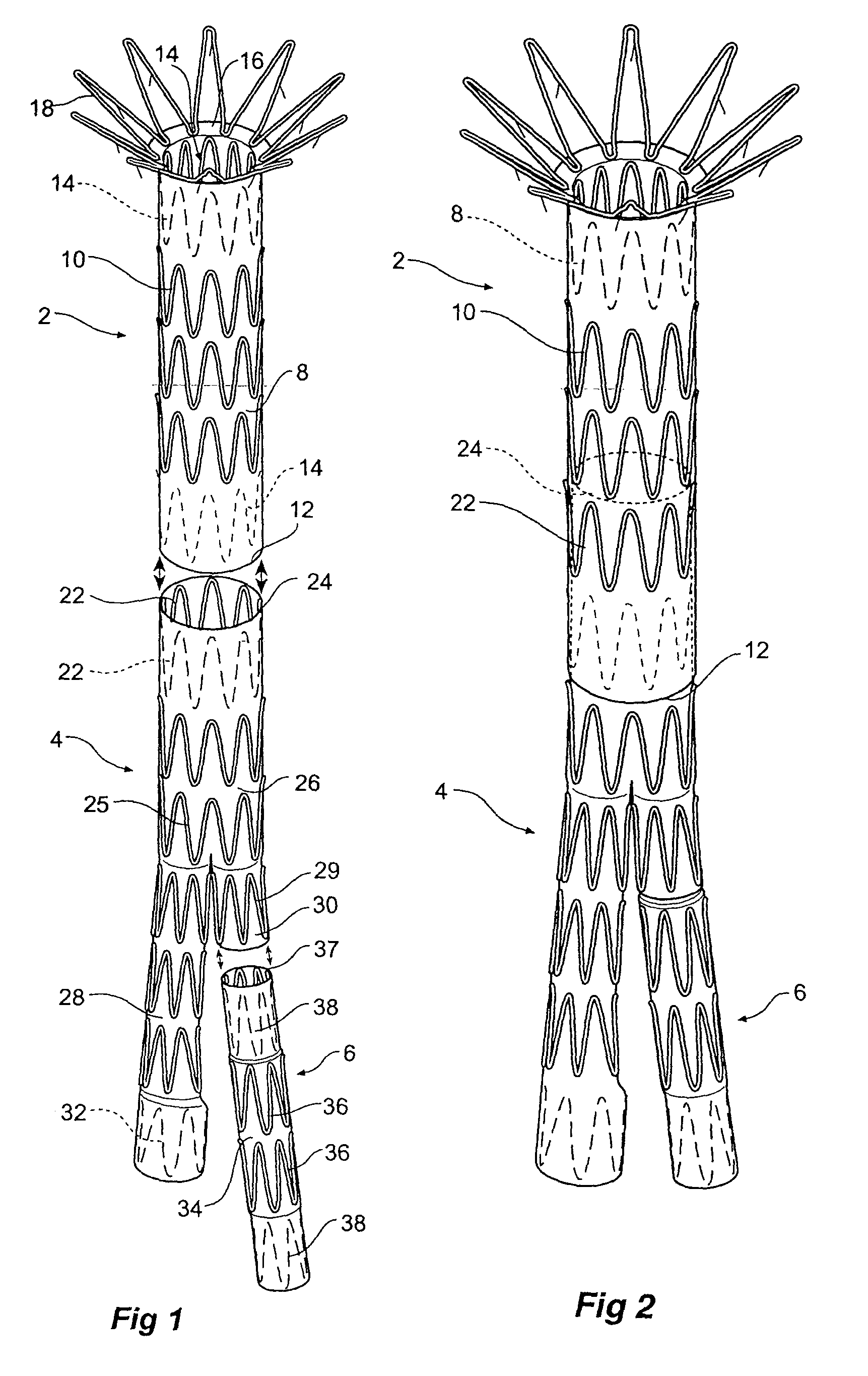
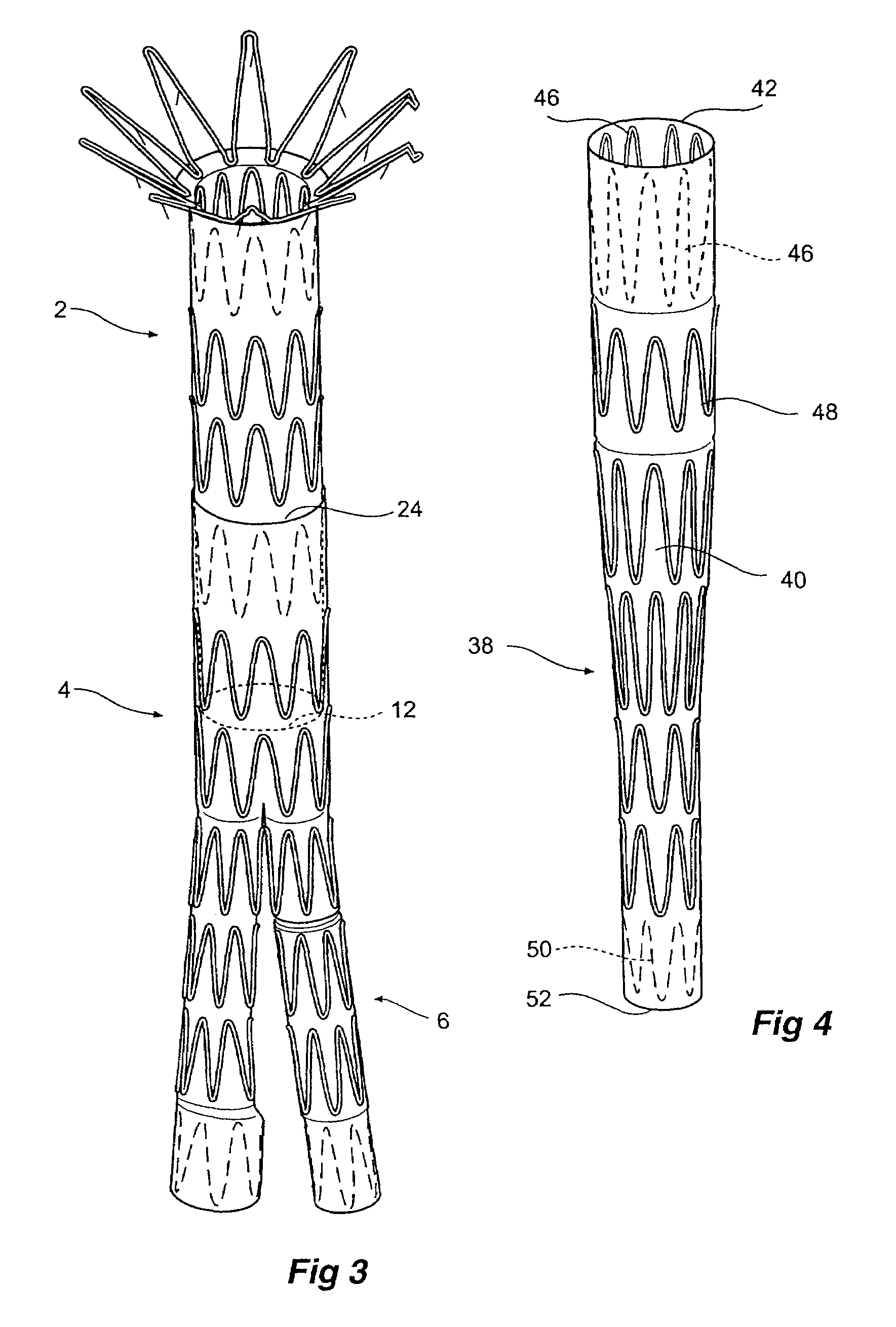
[0006]It is the object of this invention to provide a composite prosthesis which can be assembled to fit a range of lengths of aorta thereby saving inventory costs and enabling off the shelf supply of a prosthesis assembly.
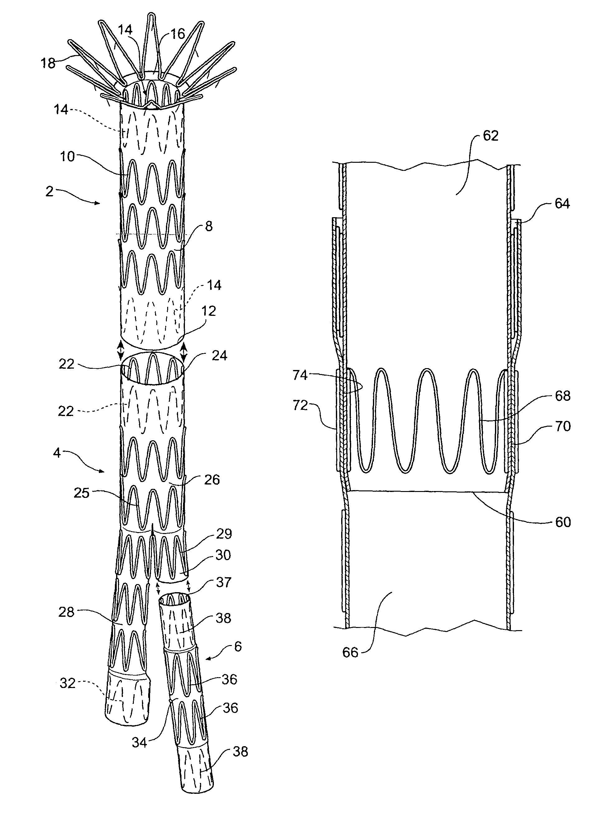
[0013]It will be seen that by these general forms of the invention the amount of overlap of the first and second or proximal and distal prosthesis can be varied thereby enabling a variety of lengths of aorta or other body lumen or the region being spanned in the aorta to be allowed for. The ability to deploy with the connecting end either inside or outside means that the either the first or second prosthesis portion can be deployed first and then the other one deployed inside it. This gives a physician considerable flexibility and means that a hospital can have a stock of prostheses which can be readily assembled depending upon the observed vasculature.
[0018]The first or proximal prosthesis portion may be provided with a proximally extending self expanding stent. Such a proximally extending self expanding stent may include barbs to engage against the wall of a lumen to hold the graft in place. This proximally extending self expanding stent may be adapted to span across the renal arteries to provide good mounting of the composite prosthesis within the aorta.

Problems solved by technology

A problem with such a prosthesis is that for different persons or animals different size prostheses must be constructed because the specific dimensions of an aorta are quite variable in each of length, diameter and angulation between the renal artery region and the region of the aortic bifurcation.

Method used


Image

  • Composite prosthesis
  • Composite prosthesis
  • Composite prosthesis

Examples


Embodiment Construction

[0031]U.S. Pat. No. 5,387,235 entitled “Expandable Transluminal Graft Prosthesis For Repair Of Aneurysm” discloses apparatus and methods of retaining grafts onto deployment devices. These features and other features disclosed in U.S. Pat. No. 5,387,235 could be used with the present invention and the disclosure of U.S. Pat. No. 5,387,235 is herewith incorporated in its entirety into this specification.

[0032]U.S. Pat. No. 5,720,776 entitled “Barb and Expandable Transluminal Graft Prosthesis For Repair of Aneurysm” discloses improved barbs with various forms of mechanical attachment to a stent. These features and other features disclosed in U.S. Pat. No. 5,720,776 could be used with the present invention and the disclosure of U.S. Pat. No. 5,720,776 is herewith incorporated in its entirety into this specification.

[0033]U.S. Pat. No. 6,206,931 entitled “Graft Prosthesis Materials” discloses graft prosthesis materials and a method for implanting, transplanting replacing and repairing a ...


PUM


Abstract

A prosthesis assembly for deployment in an aorta to span an aortic aneurysm. The prosthesis assembly has at least first and second members (2,4) with an end portion (12) of one member (2) to be joined to an end portion (24) of the other member (4) when in and when expanded within a lumen of a patient. Each member (2,4) has a stent arrangement (10,25) associated with a graft arrangement (8,26). The end portion of one member has at least part of its stent arrangement on the inner surface of its graft arrangement and the end portion of the other member has at least part of its stent arrangement on the inner surface of its graft arrangement. Advantageously two stents are overlapped. The joining portions of the first and second members can have the same diameter.

Description

CROSS-REFERENCE TO RELATED APPLICATIONS[0001]This application claims priority of provisional application Ser. No. 60 / 405,769, filed Aug. 23, 2002.TECHNICAL FIELD[0002]This invention relates to prosthesis for implantation within the human or animal body for the repair of damaged lumens such as blood vessels.BACKGROUND OF THE INVENTION[0003]Although this invention will be discussed with respect to its application to repair of abdominal aortic aneurysms the invention is not so limited and may apply to prosthesis for repair of other lumens within the human or animal body.[0004]Throughout this specification when discussing the application of this invention to the aorta the term distal with respect to a prosthesis is intended to refer to the end of the prosthesis furthest away in the direction of blood flow from the heart and the term proximal is intended to mean the end of the prosthesis which when implanted would be nearest to the heart.[0005]In our earlier patent specification publishe...

Claims


Application Information

Patent Timeline
IPC IPC(8): A61F2/06A61F2/00
CPCA61F2/07A61F2002/067A61F2002/075A61F2002/8483A61F2002/8486A61F2230/0067A61F2250/0039A61F2/89A61F2230/005A61F2230/0054A61F2250/0037
Inventor HARTLEY, DAVID ERNEST
Owner COOK MEDICAL TECH LLC
Learn More