Internal combustion engine ignition coil apparatus

a technology of ignition coil and internal combustion engine, which is applied in the direction of electrical equipment, transformers/inductance details, inductances, etc., can solve the problems of repeated stress, inability to ensure the water proofing properties inability to engage the engaging force and the progression of stiffening of the protective tube, so as to improve the water proofing effect and reduce the engagement force and the effect of stiffening

Active Publication Date: 2007-11-13
MITSUBISHI ELECTRIC CORP
View PDF12 Cites 0 Cited by
  • Summary
  • Abstract
  • Description
  • Claims
  • Application Information

AI Technical Summary

Benefits of technology

[0009]The present invention aims to solve the above problems and an object of the present invention is to provide an internal combustion engine ignition coil apparatus in which reductions in engaging force and progression of stiffening of a protective tube are suppressed so as to improve water proofing by the protective tube.
[0011]Using an internal combustion engine ignition coil apparatus having the above configuration, reductions in engaging force and progression of stiffening of a protective tube are suppressed so as to improve water proofing by the protective tube.

Problems solved by technology

In such internal combustion engine ignition coil apparatuses, engaging force of the protective tube against the rim portion is mainly due to contractive force of the leading end portion of the protective tube, but at the rim portion the protective tube may be repeatedly subjected to thermal stresses due to heat generated by the coil of the ignition coil apparatus itself, heat originating from the internal combustion engine, external air heat, etc., and may also be subjected repeatedly to stresses due to vibration.
Consequently, one problem has been that when the leading end portion of the protective tube is inserted into the rim portion, in the case of a protective tube exhibiting sudden changes due to stress, reductions in the contractive force (the engaging force) and progression of stiffening of the protective tube due to repeated thermal stresses and stresses due to vibration are each accelerated, and in some cases there is a risk that water proofing properties of the protective tube may not be ensured since the protective tube may crack, and the protective tube may move axially and disengage from the rim portion due to the reductions in the engaging force.

Method used


Image

  • Internal combustion engine ignition coil apparatus
  • Internal combustion engine ignition coil apparatus
  • Internal combustion engine ignition coil apparatus

Examples


embodiment 1

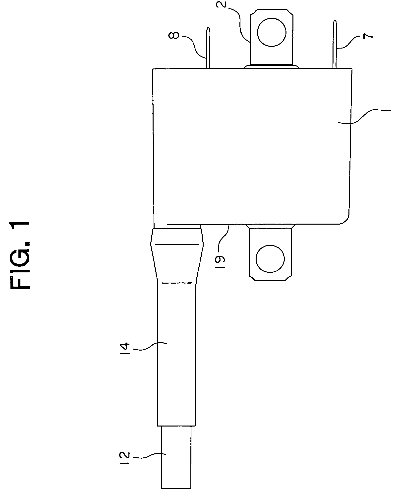
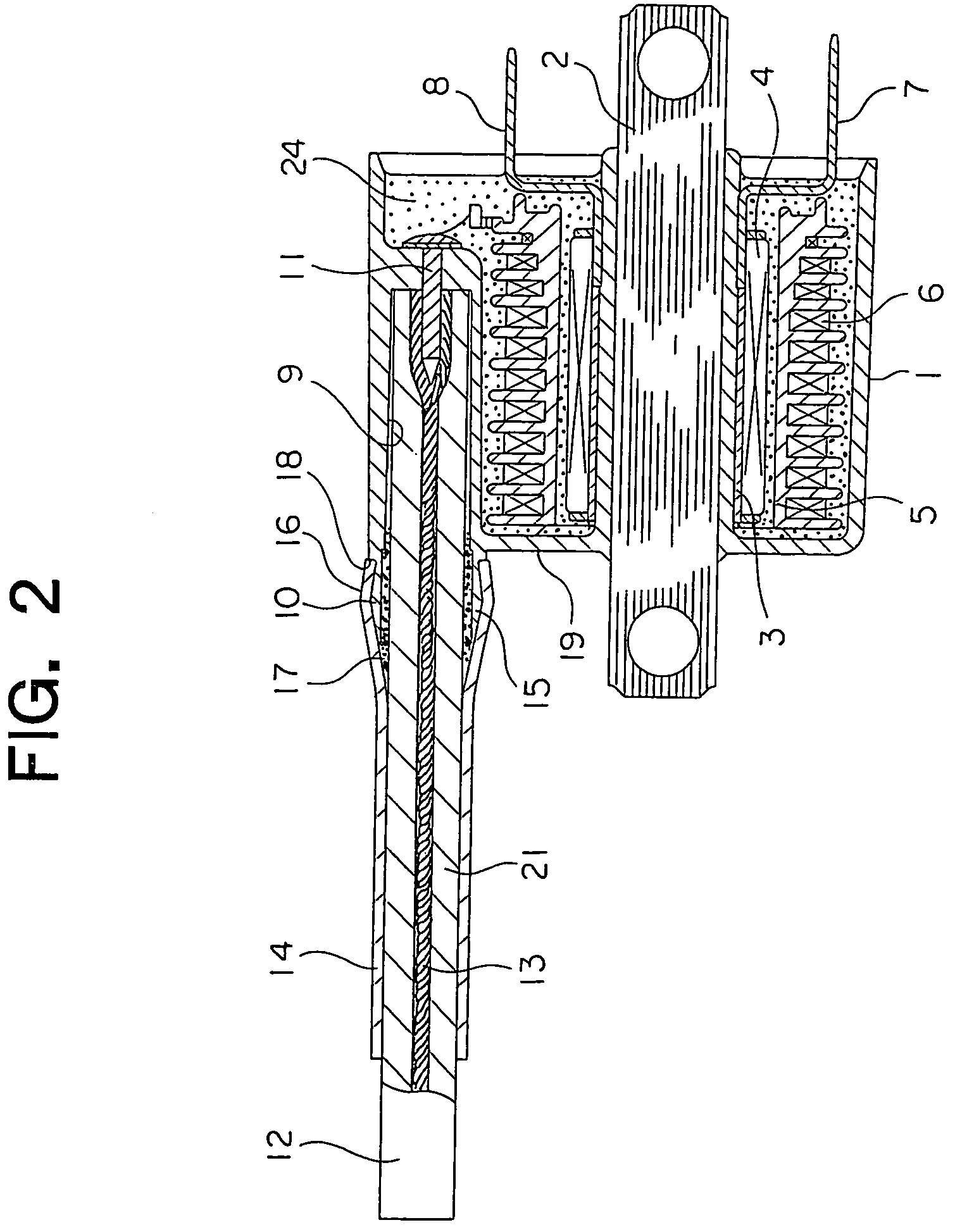
[0015]FIG. 1 is a front elevation showing an internal combustion engine ignition coil apparatus according to Embodiment 1 of the present invention; FIG. 2 is a regular cross section of FIG. 1; and FIG. 3 is an enlargement showing part of a case from FIG. 1.

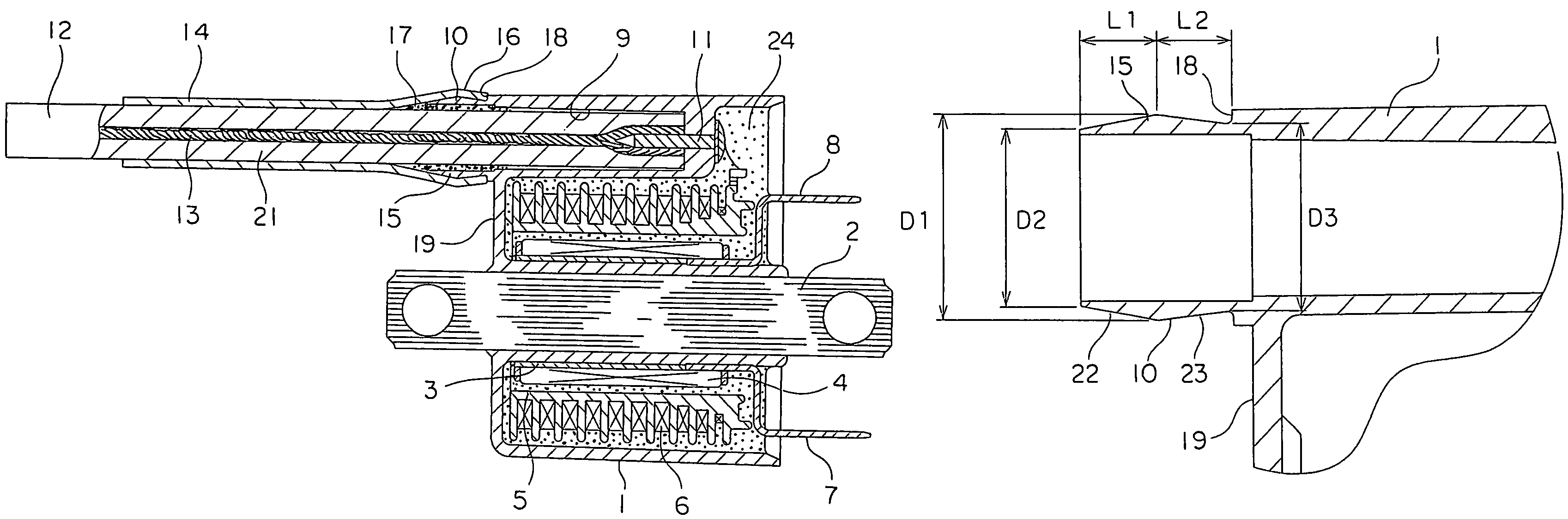
[0016]In this internal combustion engine ignition coil apparatus, a center core 2 configured by stacking electromagnetic steel plates and fixed to a vehicle body frame (not shown) is disposed in a cup-shaped case 1 so as to pass through a bottom portion 19.

[0017]A primary coil 4 configured by winding a conducting wire onto a primary bobbin 3 is disposed outside the center core 2. A secondary coil 6 configured by winding a conducting wire onto a secondary bobbin 5 is disposed outside the primary coil 4.

[0018]A winding start end portion of the conducting wire of the primary coil 4 is electrically connected to a negative terminal 7. A winding finish end portion of the conducting wire of the primary coil 4 is electrically connected to...


PUM

PropertyMeasurementUnit
axial length L2aaaaaaaaaa
voltageaaaaaaaaaa
diameteraaaaaaaaaa

Abstract

An internal combustion engine ignition coil apparatus includes: a case; a center core disposed in the case; a primary coil and a secondary coil disposed outside the center core inside the case; a high-voltage cord having: a first end portion electrically connected to the secondary coil; and a second end portion electrically connected to a spark plug; and a protective tube covering an outer peripheral surface of the high-voltage cord, a rim portion projecting away from a high-voltage terminal being formed so as to surround an insertion aperture in a bottom portion of the case, and a leading end portion of the protective tube covering and elastically engaging with the rim portion, wherein: a receiving portion having a radially-outwardly-projecting V-shaped cross-sectional shape when sectioned axially is formed on an end portion of the rim portion.

Description

BACKGROUND OF THE INVENTION[0001]1. Field of the Invention[0002]The present invention relates to an internal combustion engine ignition coil apparatus in which a high-voltage cord having a first end portion electrically connected to a secondary coil by means of a high voltage terminal and a second end portion electrically connected to a spark plug is covered by a protective tube, and a leading end portion of the protective tube is engaged elastically with a rim portion for leading out the high-voltage cord.[0003]2. Description of the Related Art[0004]Conventionally, internal combustion engine ignition coil apparatuses are known in which a groove portion formed so as to extend circumferentially is formed on an annular rim portion for leading out a high-voltage cord connected to a secondary coil by means of a high-voltage terminal, and a leading end portion of a protective tube covering an outer peripheral surface of the high-voltage cord engages with the groove portion by elastic for...

Claims


Application Information

Patent Timeline
Patent Type & Authority Patents(United States)
IPC IPC(8): H01F27/29
CPCH01T13/44H01F38/12H01F27/04
Inventor UMEZAKI, TOMOKAZUSAWAZAKI, NOBUYUKI
Owner MITSUBISHI ELECTRIC CORP
Why Eureka
Try Eureka