Computer generated hologram display system

Inactive Publication Date: 2007-11-13
INTELLECTUAL VENTURES FUND 83 LLC
View PDF36 Cites 14 Cited by
  • Summary
  • Abstract
  • Description
  • Claims
  • Application Information

AI Technical Summary

Benefits of technology

[0014]The invention therefore provides a way to have the minimal density of points consistent with the resol

Problems solved by technology

This leads to problems of non uniform density of object points across facet boundaries: too high a d

Method used


Image

  • Computer generated hologram display system
  • Computer generated hologram display system
  • Computer generated hologram display system

Examples


Embodiment Construction

[0025]Embodiments of the invention will now be described in detail, by way of example only, with reference to the accompanying drawings, in which:

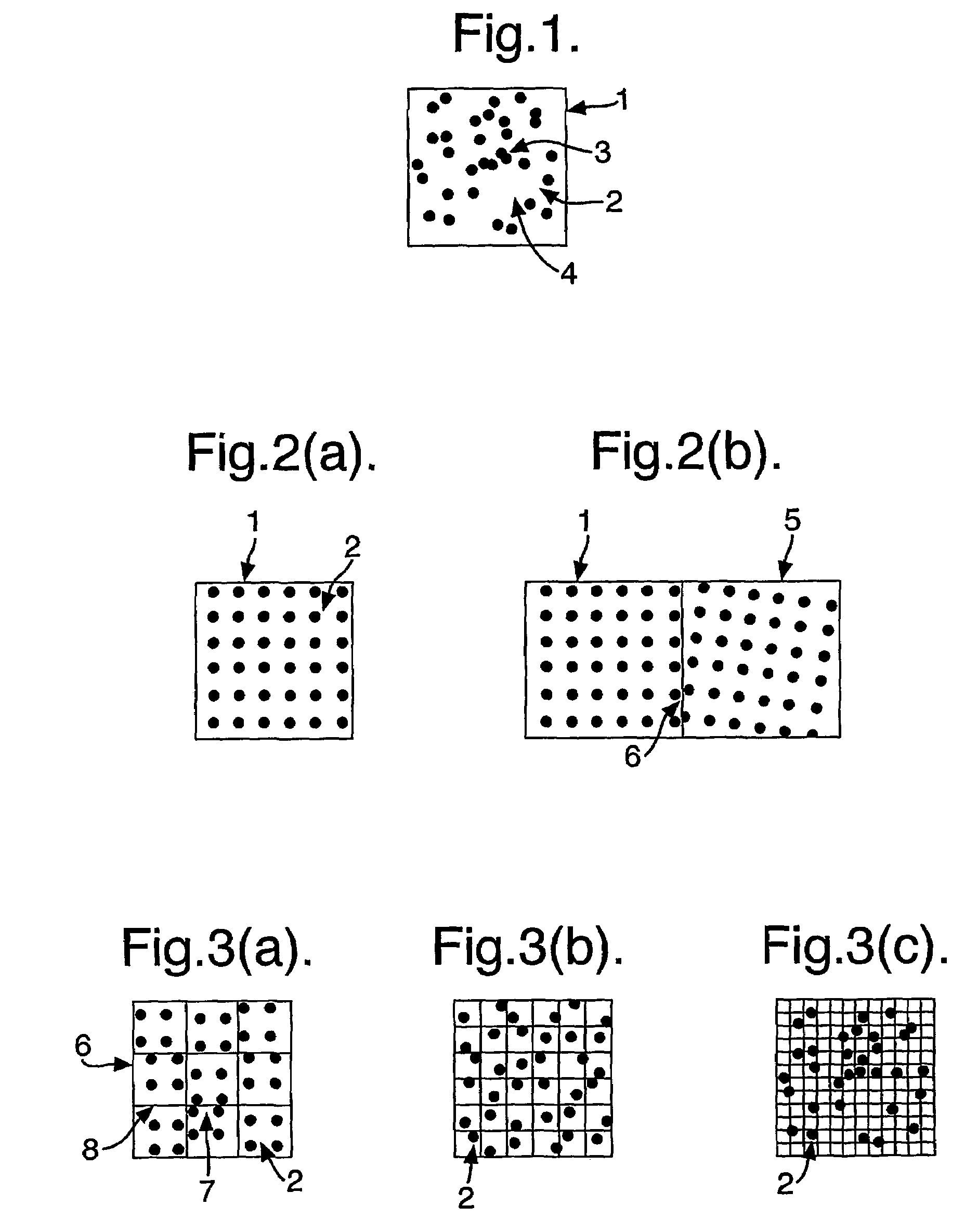
[0026]FIG. 1 diagrammatically illustrates a single facet populated with random points;

[0027]FIG. 2 diagrammatically illustrates at a) a single facet populated with a rectangular array of points, and at b) two neighbouring facets that are each populated with points on rectangular grids that each have different orientations;

[0028]FIG. 3 diagrammatically illustrates the importance of maintaining the same grid origin across multiple facets as the facet size decreases.

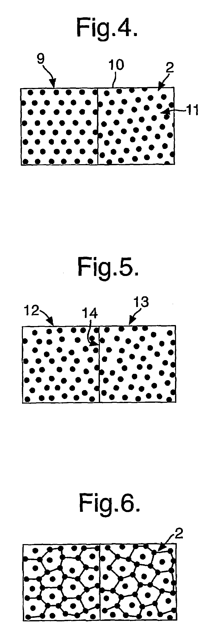
[0029]FIG. 4 diagrammatically illustrates one solution to the problem, wherein the mesh grid is laid out in the form of an equilateral triangular matrix.

[0030]FIG. 5 diagrammatically illustrates an improved mesh arrangement to that of FIG. 4

[0031]FIG. 6 diagrammatically illustrates the mesh arrangement of the points portrayed in FIG. 5

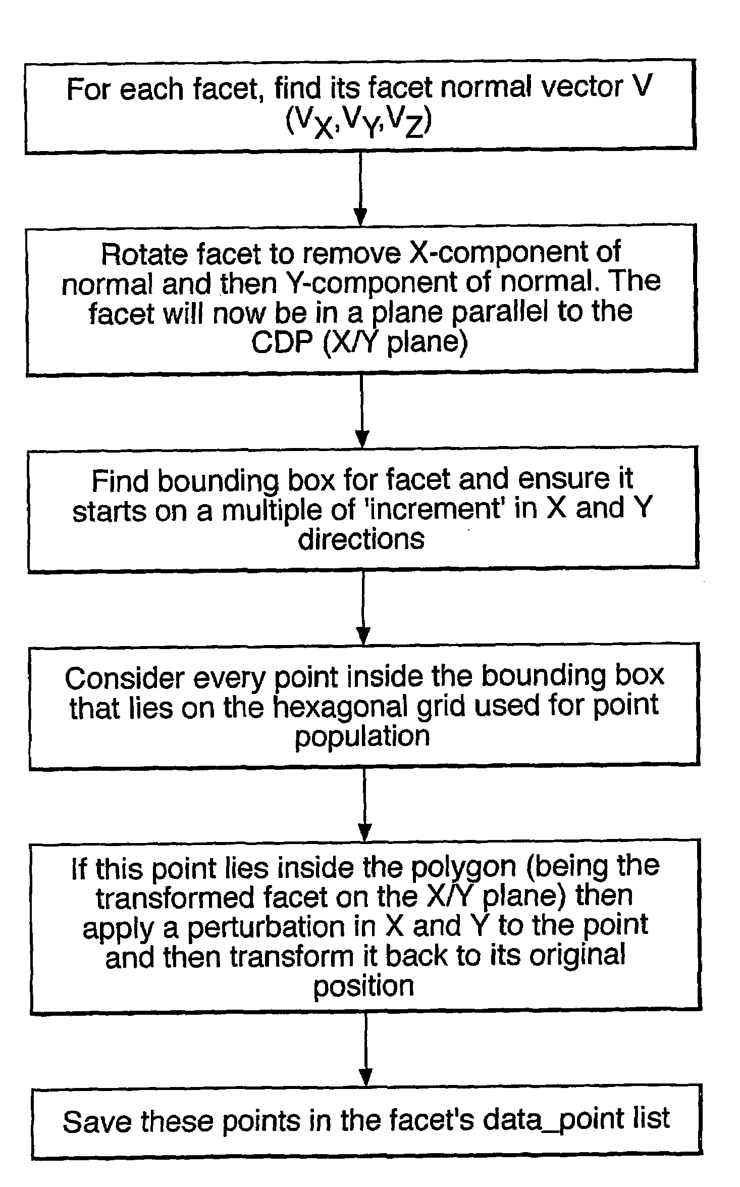
[0032]FIG. 7 shows a block diagram of the step...


PUM


Abstract

A method of displaying a computer generated hologram includes displaying the image as a set of facets that approximated to the true shape of the object to be displayed. Each of these facets is populated with points that together make up the image. The invention provides a number of array structures that allow adjoining facets at different orientations and angles to be populated with point without creating areas around the join of either point overpopulation or point underpopulation, and so results in a higher quality image. The invention is mainly applicable for producing interference base Computer Generated Holograms, but can also be used in other types of 3D display that make up objects from an array of points.

Description

[0001]This application is the US national phase of international application PCT / GB01 / 04882, filed Nov. 5, 2001, which designates the US. This application claims priority to and incorporates by reference in entirety the following applications: GB0027132.0, filed on Nov. 7, 2000 and US provisional application 60 / 247,048, filed Nov. 13, 2000.[0002]This invention relates to a method of, and system for, representing a three dimensional abject for display on a system capable of displaying objects in three dimensions. More speciffically, it relates to methods of displaying images comprising of adjoining facets, where each facet is populated, or filled, with points to give the appearance from a distance of a continuous surface.PRIOR ART [0003]In performing the calculations required to display a computer generated hologram (CGH) using an interference based algorithm, it is necessary to populate the object to be displayed with an array of points that, when seen from a suitable distance, appe...

Claims


Application Information

Patent Timeline
IPC IPC(8): G06T15/00G03H1/08G03H1/26G06T17/20G06T15/10G06T17/10
CPCG03H1/08G06T17/10G06T17/20G06T15/10G03H1/0808G03H2240/62G03H2210/441G03H2210/30
Inventor CAMERON, COLIN DCOWLING, PETER C
Owner INTELLECTUAL VENTURES FUND 83 LLC
Why Eureka
Try Eureka