Three dimensional display

a three-dimensional display and display technology, applied in the field of three-dimensional display, can solve the problems of not all facets, computation effort is needed to process each of the points, etc., and achieve the effects of reducing processing power, reducing the apparent density of points, and reducing the density of points of facets

Inactive Publication Date: 2007-02-22
MIND FUSION LLC
View PDF33 Cites 0 Cited by
  • Summary
  • Abstract
  • Description
  • Claims
  • Application Information

AI Technical Summary

Benefits of technology

[0010] If a facet is not face-on to a viewer, then the viewer of the facet will see that facet as apparently brighter, due to the increased apparent density of points. This effect gets more pronounced the further the facet normal is from the viewing zone. The density will appear greater along an axis determined by the view vector and the facet normal vector, hence the point spacing can be expanded on this axis whilst still maintaining a sufficient density for the human eye to perceive the points as a continuum.
[0011] The current invention provides for the reduction of the point density of facets that are not face-on to at least a portion of the viewing ...

Problems solved by technology

Thus, some computation effort is needed to process each of the points.
However, as the plane of each facet is in general differ...

Method used


Image

  • Three dimensional display
  • Three dimensional display
  • Three dimensional display

Examples


Embodiment Construction

[0023] One embodiment of the current invention will now be described in detail, by way of example only, with reference to the accompanying drawings, in which:

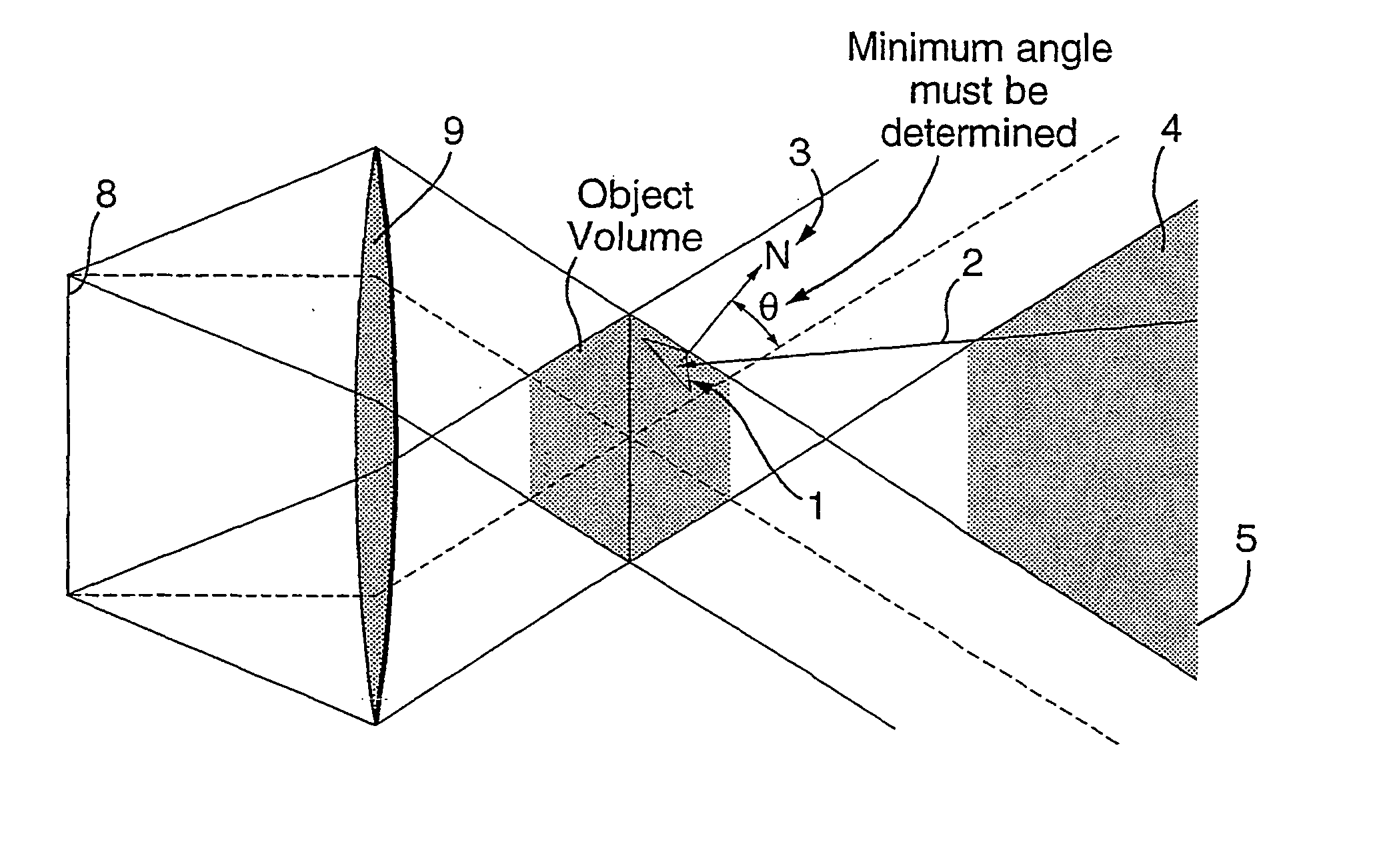
[0024]FIG. 1 diagrammatically illustrates a plan view of part of the display system, showing a facet with its normal vector N projected outside of the view volume, and a vector V projected into the view volume.

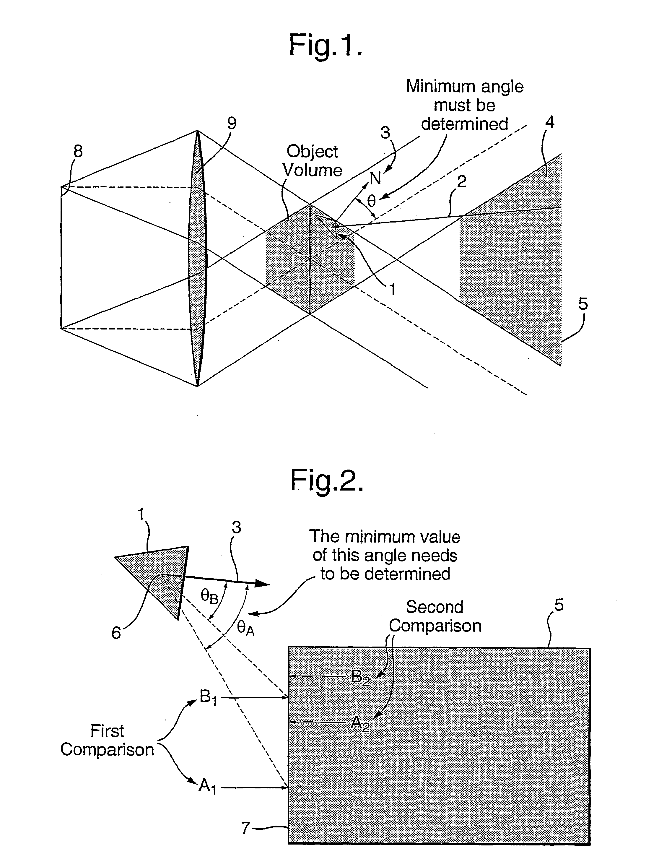
[0025]FIG. 2 illustrates the method currently used to find vector Vmin.

[0026] Each facet needs to be examined to see if dilution can be applied to it. If a facet is found to have a normal that intersects with the view volume then to maintain sufficient density over all points in the view zone, it should not have it's point density reduced, and so it will be given a dilution factor of 1.0. For convenience, the present embodiment projects a normal from the centre of the facet in question, although generally any normal can be used. As the facets are in general very small, there is little error in doing this. FIG. 1 shows a...


PUM


Abstract

The invention provides an improved means for displaying computer generated hologram (CGH). Images appearing in the image volume are realised as a set of planar facets that approximate to the shape of the original object to be displayed. These facets are populated with points, that act as the visible parts of the displayed image. When an object is displayed, certain facets will not be face on the viewing zone. This will result in an apparent surplus of points on these facets, which is wasteful of computing effort. The current invention thus provides for certain facets to be denuded of points if these facets are not presented face on to the viewing zone of the CGH. The invention is mainly applicable for producing CGHs using the interference based algorithm, but can also be used in other types of 3D display that make up objects from an array of points.

Description

[0001] This invention relates to a method of, and system for, representing three-dimensional objects. More specifically, it relates to methods of reducing the large computational loads associated with the computation of computer generated holograms when parts of three dimensional objects are not presented fully face-on to the observer. It also relates to systems capable of implementing the methods presented. PRIOR ART [0002] In performing the calculations required to display a computer generated hologram (CGH), it is necessary to populate the object to be displayed with an array of points that, when seen from a suitable distance, appear as a continuum. It is usual in computer graphics fields to quantize the object to be displayed into a series of planar facets that approximate to the actual shape. The points that make up the object are populated onto these facets. An observer viewing such an object from a sufficiently large distance will tend to see not the individual points but ins...

Claims


Application Information

Patent Timeline
IPC IPC(8): G06T15/00G03H1/08G03H1/26G06T19/00G09G3/00
CPCG03H1/08G03H1/0808G03H2210/441G03H2210/452G03H2240/62G09G3/001G03H2210/30
Inventor CAMERON, COLIN D.COWLING, PETER C.
Owner MIND FUSION LLC
Why Eureka
Try Eureka