Thermal response correction system

a correction system and thermal technology, applied in printing and other directions, can solve the problems of affecting the quality of affecting the quality of reducing the density of the output produced by the print head element,

Inactive Publication Date: 2007-11-13
TPP TECH LLC
View PDF58 Cites 21 Cited by
  • Summary
  • Abstract
  • Description
  • Claims
  • Application Information

AI Technical Summary

Problems solved by technology

One problem with conventional thermal printers results from the fact that their print head elements retain heat after the conclusion of each print head cycle.
This retention of heat can be problematic because, in some thermal printers, the amount of energy that is delivered to a particular print head element during a particular print head cycle is typically calculated based on an assumption that the print head element's temperature at the beginning of the print head cycle is a known fixed temperature.
Further complications are similarly caused by the fact that the current temperature of a particular print head element is influenced not only by its own previous temperatures—referred to herein as its “thermal history”—but by the ambient (room) temperature and the thermal histories of other print head elements in the print head.
This gradual temperature increase results in a corresponding gradual increase in density of the output pro

Method used


Image

  • Thermal response correction system
  • Thermal response correction system
  • Thermal response correction system

Examples


Embodiment Construction

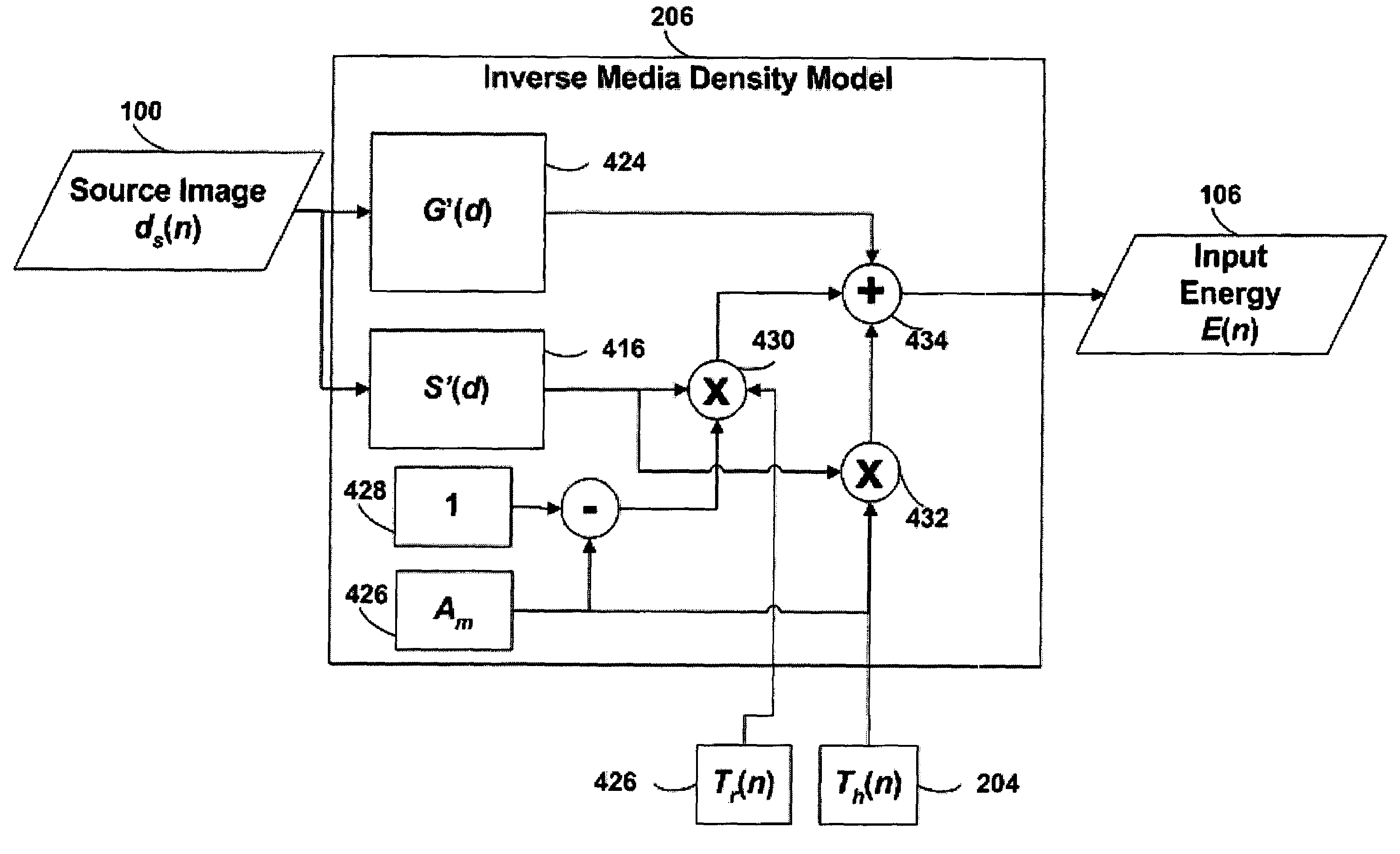
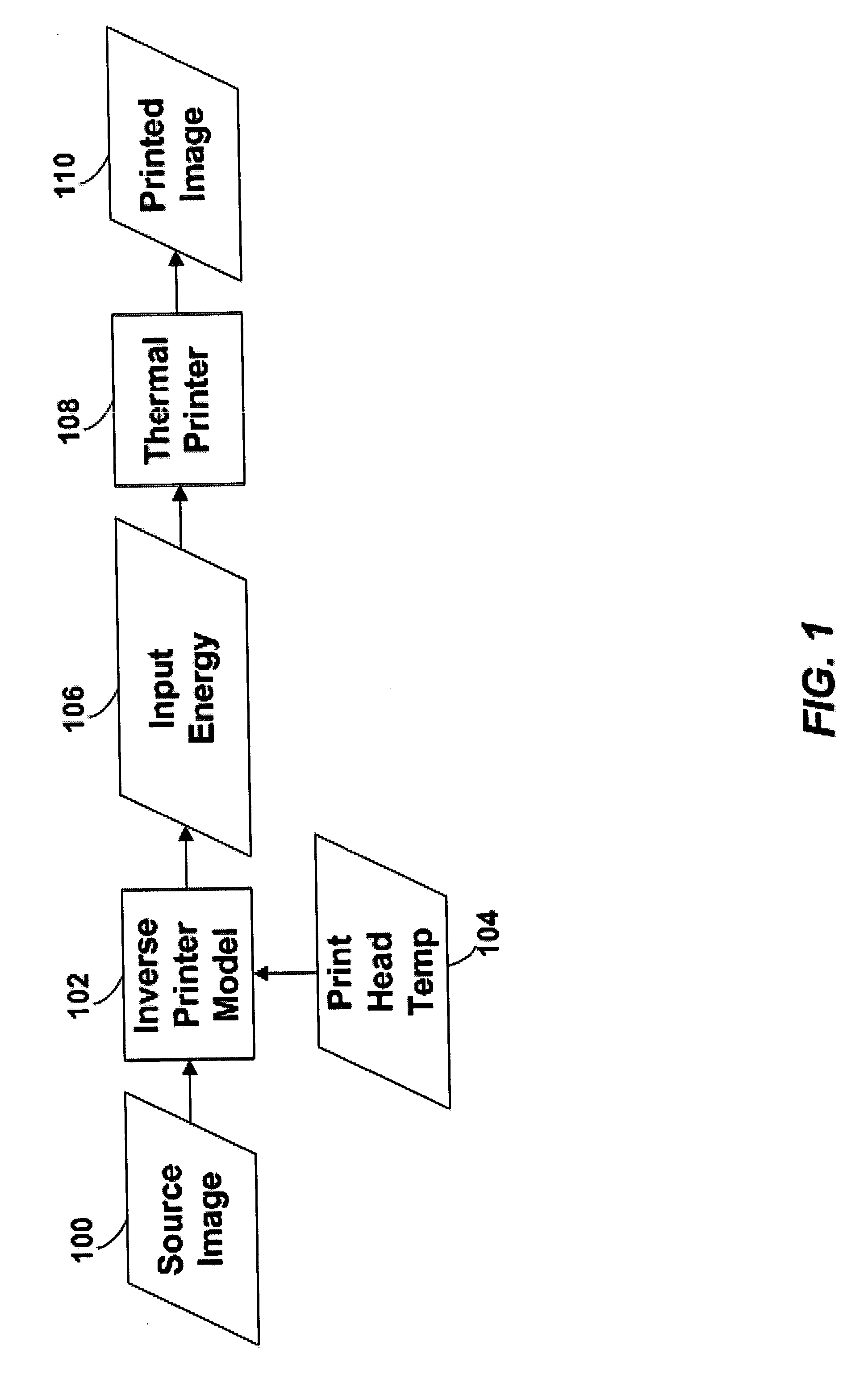
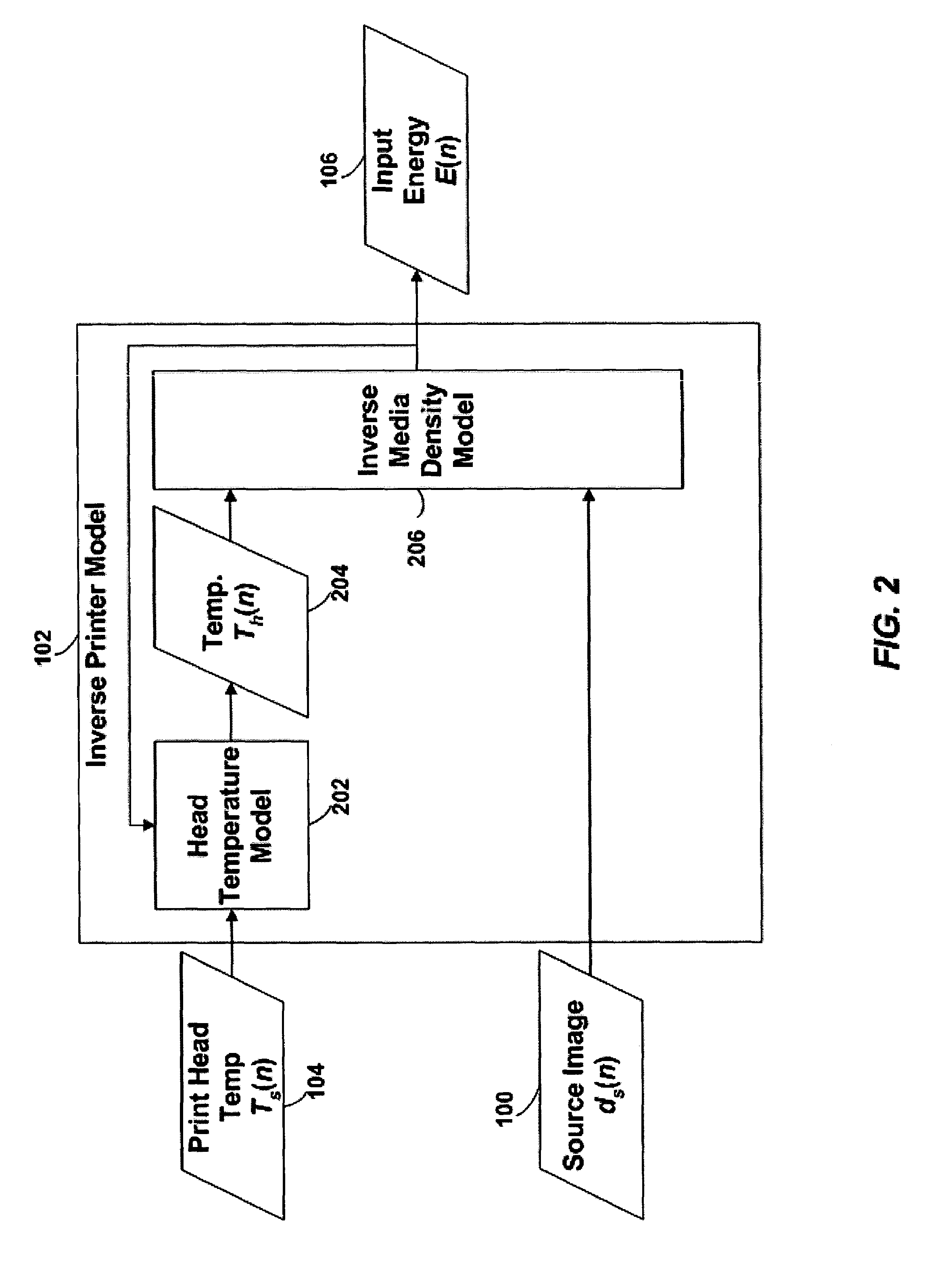
[0026]A model of a thermal print head is provided that models the thermal response of thermal print head elements to the provision of energy to the print head elements over time. The amount of energy to provide to each of the print head elements during a print head cycle to produce a spot having the desired density is calculated based on: (1) the desired density to be produced by the print head element during the print head cycle, (2) the predicted temperature of the print head element at the beginning of the print head cycle, (3) the ambient printer temperature at the beginning of the print head cycle, and (4) the ambient relative humidity.

[0027]The above-referenced patent application entitled “Thermal Response Correction System” disclosed a model of a thermal print head that models the thermal response of thermal print head elements to the provision of energy to the print head elements over time. The history of temperatures of print head elements of a thermal print head is referre...


PUM


Abstract

A model of a thermal print head is provided that models the thermal response of thermal print head elements to the provision of energy to the print head elements over time. The amount of energy to provide to each of the print head elements during a print head cycle to produce a spot having the desired density is calculated based on: (1) the desired density to be produced by the print head element during the print head cycle, (2) the predicted temperature of the print head element at the beginning of the print head cycle, (3) the ambient printer temperature at the beginning of the print head cycle, and (4) the ambient relative humidity.

Description

CROSS REFERENCE TO RELATED APPLICATIONS[0001]This application is a continuation-in-part of U.S. patent application Ser. No. 09 / 934,703, filed on Aug. 22, 2001, entitled “Thermal Response Correction System,” now U.S. Pat. No. 6,819,347 B2, which is hereby incorporated by reference.BACKGROUND[0002]1. Field of the Invention[0003]The present invention relates to thermal printing and, more particularly, to techniques for improving thermal printer output by compensating for the effects of thermal history on thermal print heads.[0004]2. Related Art[0005]Thermal printers typically contain a linear array of heating elements (also referred to herein as “print head elements”) that print on an output medium by, for example, transferring pigment or dye from a donor sheet to the output medium or by activating a color-forming chemistry in the output medium. The output medium is typically a porous receiver receptive to the transferred pigment, or a paper coated with the color-forming chemistry. Eac...

Claims


Application Information

Patent Timeline
IPC IPC(8): B41J2/365B41J2/05B41J2/07B41J2/36
CPCB41J2/3555B41J2/365B41J2/36B41J2/35
Inventor BUSCH, BRIAN D.SAQUIB, SUHAIL S.VETTERLING, WILLIAM T.
Owner TPP TECH LLC
Why Eureka
Try Eureka