
Hydraulic service module

a technology of hydraulic fluid and service module, which is applied in the direction of fluid couplings, hybrid vehicles, jet propulsion mounting, etc., can solve the problems of high cost, less mass and volume, and serious problems for fitting on motor vehicles

Inactive Publication Date: 2007-11-20
BOSCH REXROTH AG
View PDF15 Cites 21 Cited by
  • Summary
  • Abstract
  • Description
  • Claims
  • Application Information

AI Technical Summary

Benefits of technology

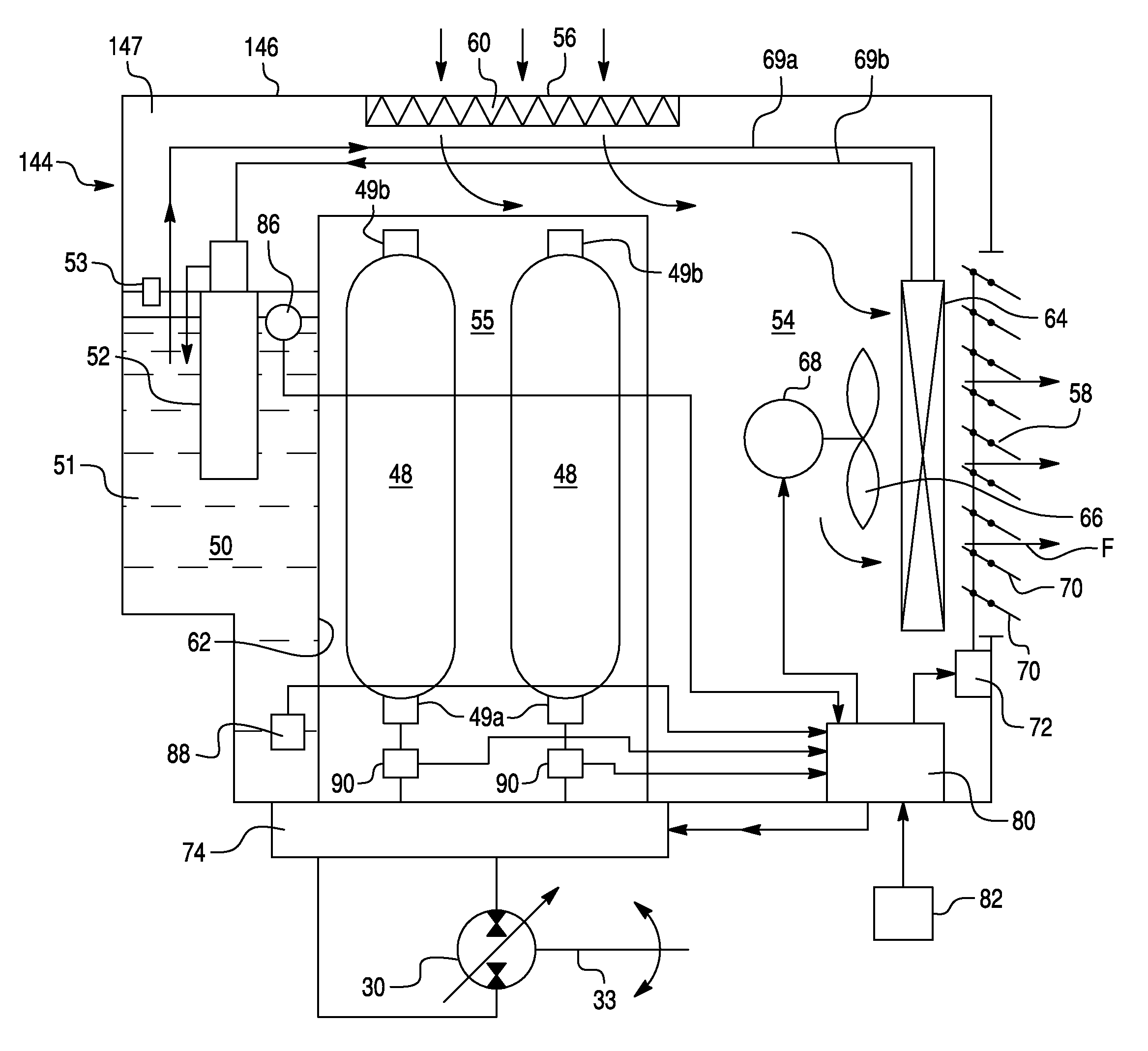
"The present invention provides a hydraulic service module for use in a hydraulic fluid system of a motor vehicle. The module includes a housing with an air chamber and a heat exchanger for cooling the hydraulic fluid. It also includes a cooling fan for forced cooling and a valve manifold for selectively connecting the accumulators and the fluid reservoir. The module has an air inlet port and an air filter for removing contaminants from air entering the air chamber. The hydraulic service module integrates and modularizes the bulk of the essential components of the hydraulic regenerative drive system, other than those that convert mechanical energy to and from hydraulic energy and those that connect to the driveline of the motor vehicle."

Problems solved by technology

On the other hand they remain less efficient in terms of mass and volume and consequently raise serious problems for fitting onto motor vehicles.
In addition to penalizing the energy savings obtained, these problems of dead weight and bulk lead to high costs linked either with the hydraulic fluid accumulator itself or, mainly, with the modifications that have to be made to the vehicle to fit the accumulator.
The result is that the motor vehicles equipped with the hydraulic fluid accumulator are no longer standard in any way and are therefore much more expensive to produce and maintain and that, furthermore, the equipment used for this installation cannot be transposed to another vehicle or modulated in size, which increases the overall cost of such an installation.
In the existing vehicles equipped with the hydraulic regenerative drive system, the necessary system components are distributed around the vehicle in a fashion that would be unacceptable in a production system.
Moreover, the primary design challenge lies in the fact that some motor vehicles have several variants.

Method used


Image

  • Hydraulic service module
  • Hydraulic service module
  • Hydraulic service module

Examples


Embodiment Construction

[0028]The preferred embodiment of the present invention will now be described with the reference to accompanying drawings.

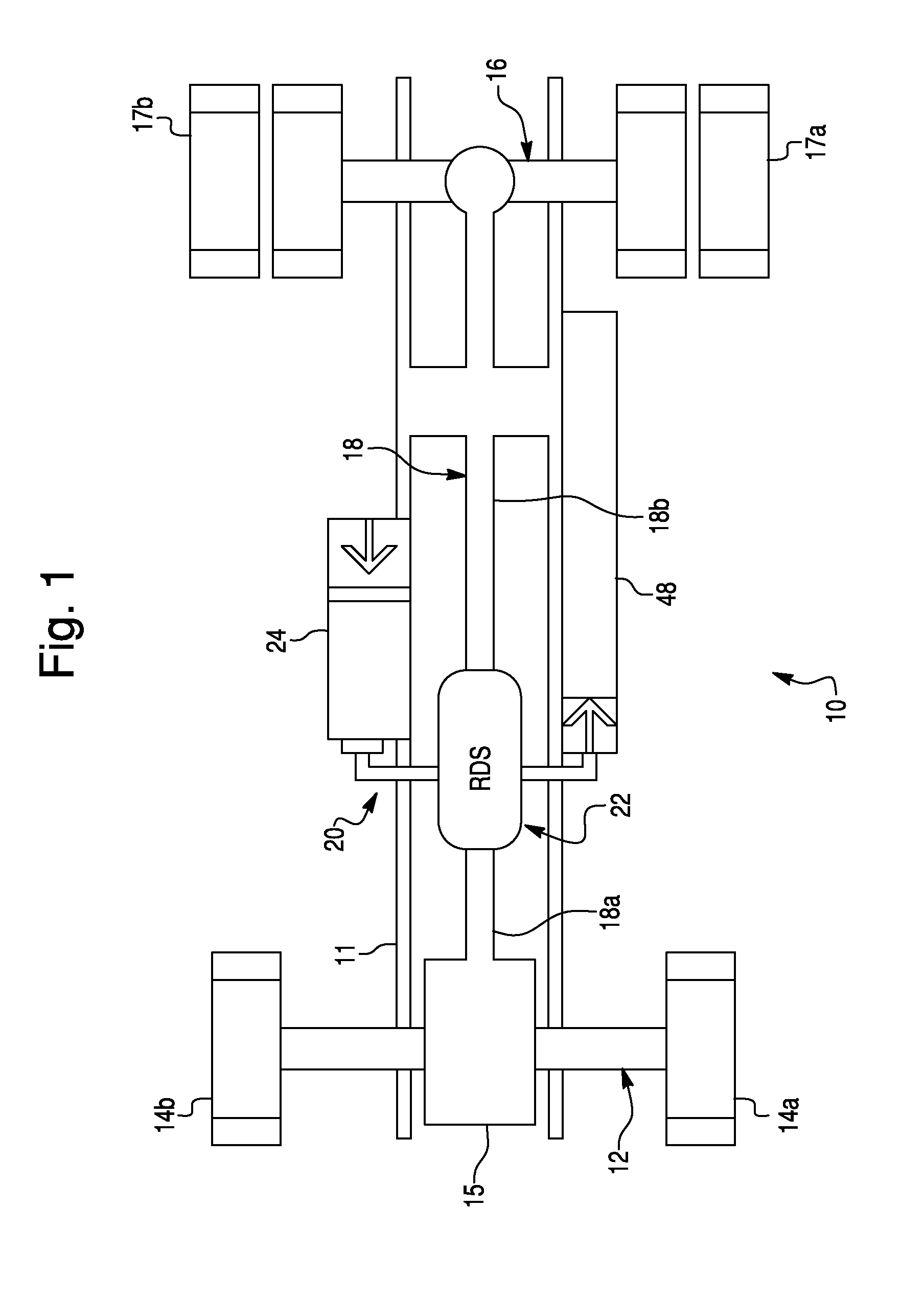
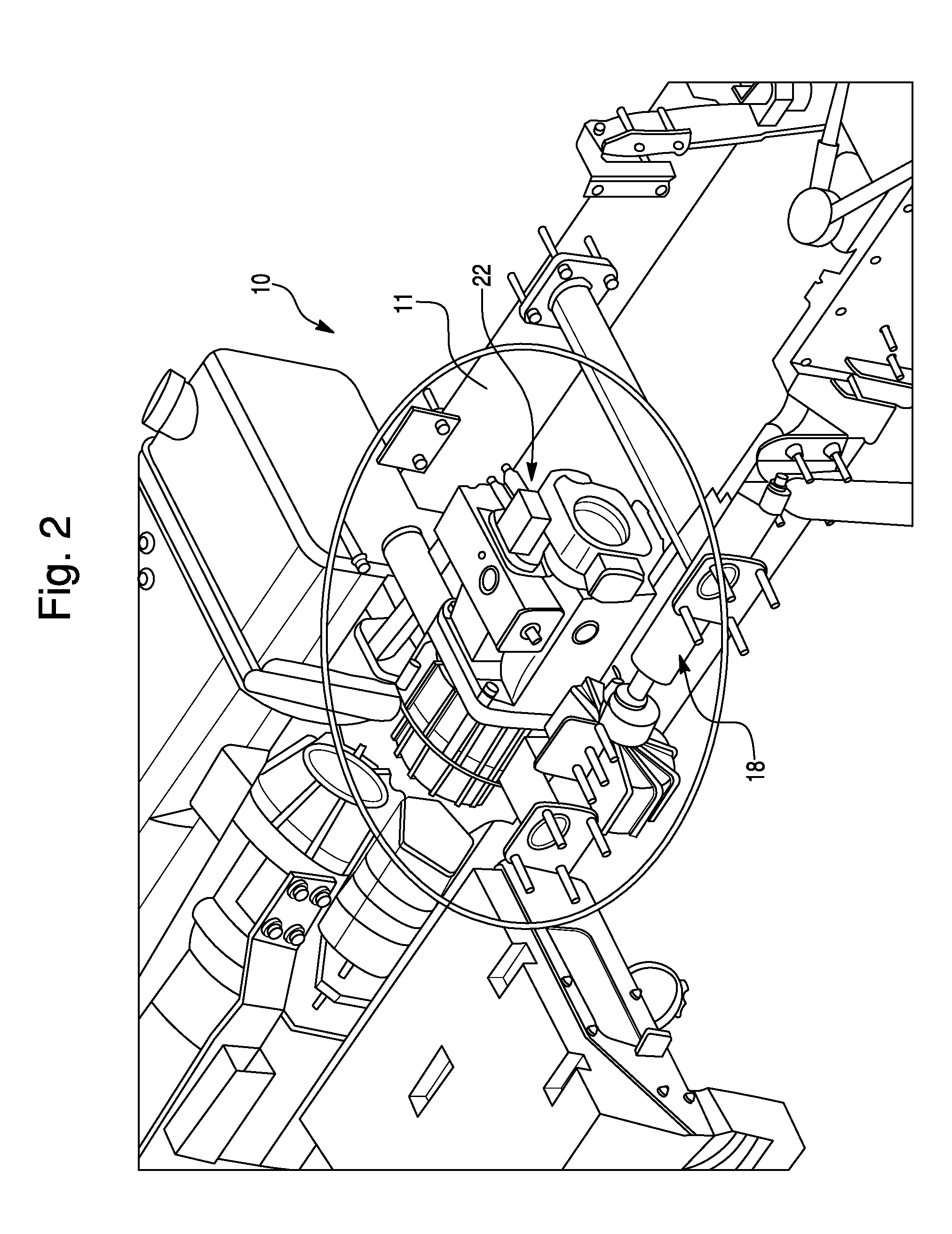
[0029]FIG. 1 depict a motor vehicle 10 equipped with a hydraulic fluid system in the form of a hydraulic regenerative drive system 20 in accordance with the preferred embodiment of the present invention. As illustrated, the motor vehicle 10 comprises a front axle 12 having wheels 14a and 14b, a rear drive axle 16 having wheels 17a and 17b driven by a prime mover 15, such as an internal combustion engine, through a driveline 18.

[0030]The hydraulic regenerative drive system 20 includes a low-pressure fluid reservoir 24, a high-pressure hydraulic accumulator 26 and a hydraulic regenerative drive unit 22 in fluid communication with both the low-pressure fluid reservoir 24 and the high-pressure accumulator 26. The fluid reservoir 24 of the hydraulic regenerative drive system 20, shown in FIG. 1, and contains an appropriate amount of a hydraulic working fluid, such as ...


PUM


Abstract

A hydraulic service module is provided for a hydraulic fluid system, which includes a fluid reservoir for storing an appropriate amount of a hydraulic fluid. The hydraulic service module comprises an outer casing defining an enclosure therewithin including an air chamber in fluid communication with an ambient air. The hydraulic service module houses one or more fluid pressure accumulators mounted within the enclosure and a heat exchanger provided for cooling the hydraulic fluid.

Description

CROSS-REFERENCE TO RELATED APPLICATION[0001]This Application claims the benefit under 35 U.S.C. 119(e) of U.S. Provisional Application No. 60 / 550,315 filed on Mar. 8, 2004 by Kenric Rose.BACKGROUND OF THE INVENTION[0002]1. Field of the Invention[0003]The present invention relates to hydraulic fluid systems in general, such as hydraulic regenerative drive systems, and, more particularly, to a service module for a hydraulic fluid system including a hydraulic service module containing at least one hydraulic fluid accumulator.[0004]2. Description of the Prior Art[0005]In conventional integrated pressurized fluid systems the recovered energy is normally accumulated in flywheel accumulators, in electrochemical batteries or in hydraulic fluid accumulators. The latter are of known technology and, in comparison with the other recovery and accumulation arrangements, they are more flexible in use, notably in connection with a vehicular transmission to which they are connected. On the other han...

Claims


Application Information

Patent Timeline
Patent Type & Authority Patents(United States)
IPC IPC(8): F16D31/02B60K5/00B60K6/12F15B1/02F15B1/26F15B21/0423
CPCB60K6/12F15B1/024F15B1/26F15B2211/6343F15B2211/20569F15B2211/625F15B2211/6306F15B2211/6303F15B21/0423Y02T10/62F15B21/042
Inventor ROSE, KENRIC B.
Owner BOSCH REXROTH AG
Learn More