Method for determination of fuel thermal stability

a fuel thermal stability and method technology, applied in the direction of fluorescence/phosphorescence, luminescent dosimeters, optical radiation measurement, etc., can solve the problems of inapplicability of models, researchers have developed models that are not universally applicable, and the routine analysis takes too long. , to achieve the effect of eliminating needless testing

Active Publication Date: 2007-11-20
PETROLEUM ANALYZER COMPANY
View PDF5 Cites 10 Cited by
  • Summary
  • Abstract
  • Description
  • Claims
  • Application Information

AI Technical Summary

Benefits of technology

[0008]In one broad respect, the present invention is a method of evaluating thermal stability of a fuel, comprising heating the fuel to a given temperature, directing light through the heated fuel a first time wherein the light is of an intensity and of a wavelength to induce fluorescence of the fuel and obtaining a first fluorescence data, directing the light through the fuel at least a second time that is later in time and obtaining a second fluorescence data, and measuring any changes to fluorescence from the heated fuel over time. The fuel sample is thus illuminated with the light from the energy source and the fluorescence observed and measured. The data from the at least two illumination times will provide a plot of fluorescence versus time which can be compared with a database of plots at given breakpoints for a given fuel to determine whether the fuel should be, for example, further tested with the JFTOT method. The method of this invention allows both qualitative and quantitative evaluation of the fuel.
[0011]This invention provides a relatively quick, routine screening tool that can eliminate needless testing using JFTOT on otherwise good fuel and ensure testing of potentially bad fuels that would have been overlooked.

Problems solved by technology

If there is a suspicion of a problem, the JFTOT is employed but it takes too much time for routine analysis.
However, U.S. Pat. No. 5,198,871 provided no correlation between the fluorescence and the thermal stability.
Moreover, past researchers have attempted to describe the chemistry of deposition with limited success.
Specifically, the past researchers developed models that were not universally applicable.

Method used


Image

  • Method for determination of fuel thermal stability
  • Method for determination of fuel thermal stability
  • Method for determination of fuel thermal stability

Examples


Embodiment Construction

[0017]A basic system that may be employed in the practice of this invention is shown in U.S. Pat. No. 5,198,871, incorporated herein by reference. The system shown in U.S. Pat. No. 5,198,871 lacks, however, a heater within the system that is used to heat samples to a given temperature in the practice of this invention. The present inventors have recognized the advantages of heating the fuel samples prior to or concurrent with directing light of an appropriate wavelength and intensity at the fuel.

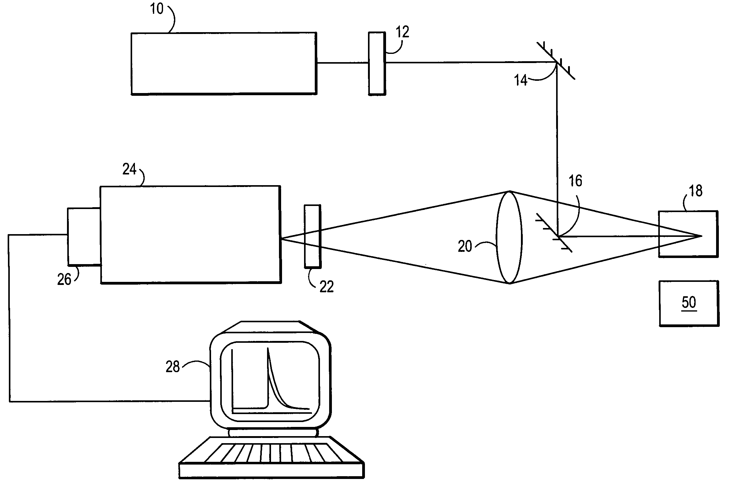
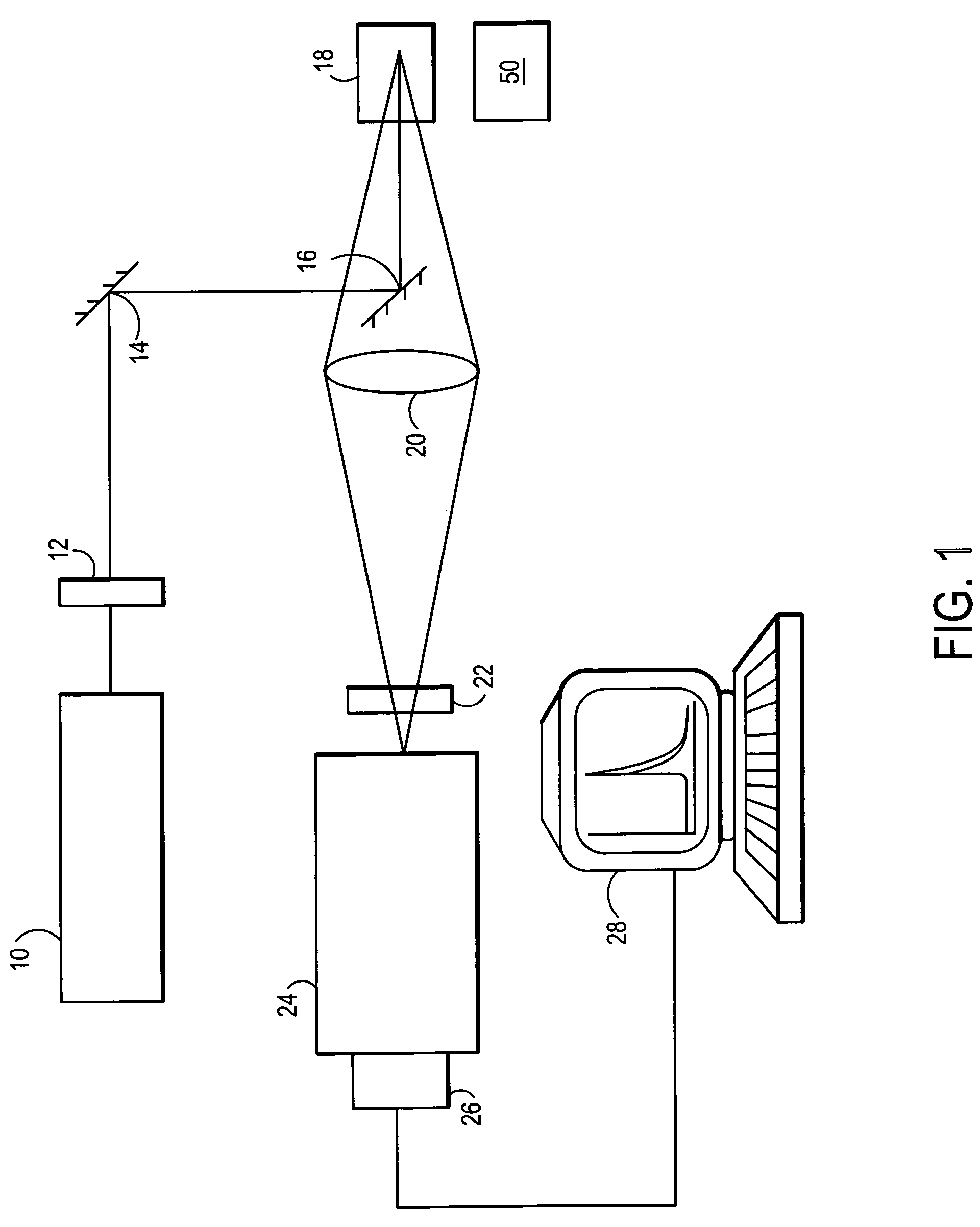
[0018]A system that can be used in the practice of this invention is depicted in FIG. 1. In FIG. 1, light from an excitation source 10 is passed through a filter 12 and reflected by mirrors 14 and 16 to illuminate a fuel sample 18 to be tested for fluorescence. In one embodiment, the energy source 10 is a laser having a suitable wavelength to cause fluorescence. The energy source can be blue light in the wavelength range of 440-500 nanometers (nm), such as from the 488 nm line of an Argon ga...


PUM

PropertyMeasurementUnit
temperaturesaaaaaaaaaa
temperatureaaaaaaaaaa
wavelengthaaaaaaaaaa

Abstract

A method of evaluating thermal stability of a fuel and an apparatus used therein. The method includes heating the fuel to a given temperature, directing light through the heated fuel a first time wherein the light is of an intensity and of a wavelength to induce fluorescence and obtaining a first fluorescence data, directing the light through the fuel at least a second time that is later in time and obtaining a second fluorescence data, and measuring any changes to fluorescence from the heated fuel over time.

Description

[0001]This application claims priority to U.S. Provisional Application Ser. No. 60 / 676,881, filed May 2, 2005, incorporated herein in its entirety by reference.FIELD OF INVENTION[0002]This invention relates to an apparatus and method for determining the thermal stability of a fuel such as aviation fuel using light induced fluorescence.BACKGROUND OF THE INVENTION[0003]The relative thermal stability of jet fuel is an important factor in practice. The standard test for this property, the JFTOT method (ASTM D3241), is used as a qualitative test to determine whether the fuel can be used. This test method covers the procedure for rating the tendencies of gas turbine fuels to deposit decomposition products within the fuel system. The fuel is tested at a required minimum temperature to determine if it meets minimum acceptance criteria. The JFTOT test basically determines whether the fuel passes or fails the test based on the breakpoint of the fuel. The breakpoint method requires running mul...

Claims


Application Information

Patent Timeline
Patent Type & Authority Patents(United States)
IPC IPC(8): G01N21/64
CPCG01N21/6402G01N33/2805Y10T436/218G01N2021/6417
Inventor MOSES, CLIFFORD A.NAEGELI, DAVID W.WILSON, III, GEORGE R.
Owner PETROLEUM ANALYZER COMPANY
Why Eureka
Try Eureka