Methods and systems for electronic component test time improvement

a technology of electronic components and test time, applied in the direction of oscillator generators, pulse automatic control, instruments, etc., can solve the problems of high undesirable time-consuming operation, high cost of production time expenditure, and time-consuming operation, so as to avoid significant time expenditure, avoid time expense, and avoid time expense

Active Publication Date: 2007-11-20
NAT SEMICON CORP
View PDF1 Cites 0 Cited by
  • Summary
  • Abstract
  • Description
  • Claims
  • Application Information

AI Technical Summary

Benefits of technology

[0005]Accordingly, a need exists for a method and system that can help to speed electronic component test time in the production test environment. The present invention provides a method and system that accomplishes this need.
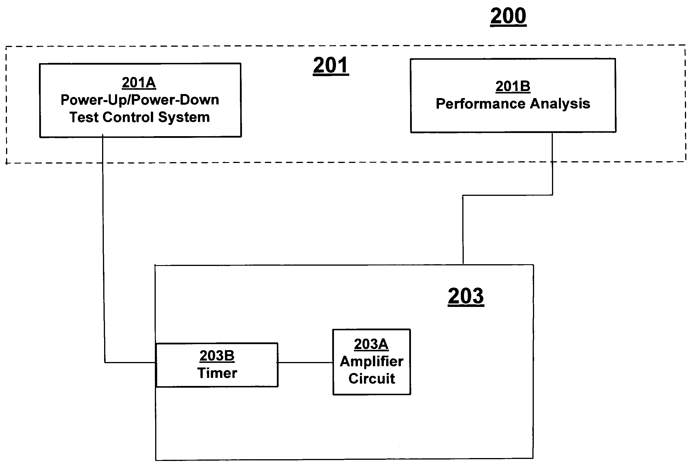
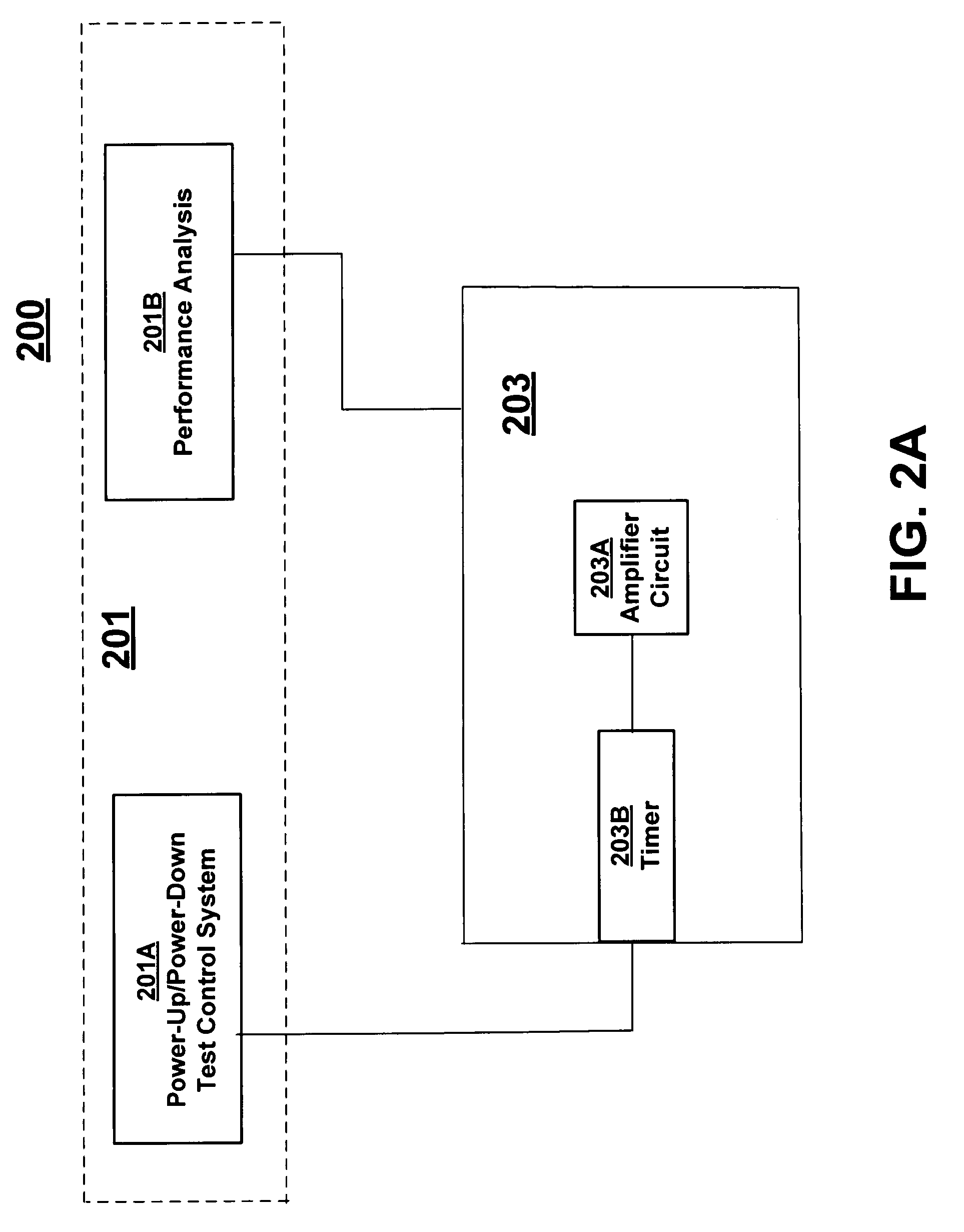
[0007]In one embodiment, respective portions of a timer circuit are tested during respective phases of a production test such that a testing of the entire timer circuit is effected in a single power-up / power-down cycle of the production test, and time expenditures related to a testing of the entire timer completely in each single phase of the production test is avoided. In one embodiment, only a first portion of the timer circuit is tested in a power-up phase of a testing cycle thereby avoiding the time expense that would be incurred by testing both a first and a second portion of the timer circuit in the power-up phase of the testing cycle. Likewise, only a second portion of the timer circuit is tested in a power-down phase of the testing cycle thereby avoiding the time expense that would be incurred by testing both the first and the second portion of the timer circuit in the power-down phase of the testing cycle. By testing only a first portion of timer circuit in the power-up phase and only a second portion of timer circuit in the power-down phase, a testing of the entire timer circuit can be effected while significant time expenditures can be avoided in each phase of the testing cycle.

Problems solved by technology

Each test that is performed on a part exacts a cost in terms of time expenditure.
The time expenditure for each part, or component of a part is multiplied over large numbers of parts and thus can be very expensive.
These wait times, that are expended on each part, constitute production time expenditures that are very costly in terms of time and expense.
Such time consuming operation is highly undesirable in the production test environment.

Method used


Image

  • Methods and systems for electronic component test time improvement
  • Methods and systems for electronic component test time improvement
  • Methods and systems for electronic component test time improvement

Examples


Embodiment Construction

[0021]Reference will now be made in detail to embodiments of the invention, examples of which are illustrated in the accompanying drawings. While the invention will be described in conjunction with these embodiments, it will be understood that they are not intended to limit the invention to these embodiments. On the contrary, the invention is intended to cover alternatives, modifications and equivalents, which may be included within the spirit and scope of the invention as defined by the appended claims. Furthermore, in the following detailed description of the present invention, numerous specific details are set forth in order to provide a thorough understanding of the present invention. However, the present invention may be practiced without these specific details. In other instances, well known methods, procedures, components, and circuits have not been described in detail as not to unnecessarily obscure aspects of the present invention.

System for Electronic Component Test Time I...


PUM


Abstract

A timer circuit that has a normal mode and a test mode is disclosed. The test mode includes a power-up phase and a power-down phase. The timer circuit includes an oscillator and a first timer circuit portion coupled to the oscillator. The first timer circuit portion includes an input and an output. An output signal that confirms either the satisfactory or unsatisfactory operation of the first timer circuit portion is taken from the output associated with the first timer circuit portion in the power-up phase. The timer circuit further includes a second timer circuit portion coupled to the first timer circuit portion and the oscillator. The second timer circuit portion also includes an input and an output. An output signal that confirms either the satisfactory or unsatisfactory operation of the second timer circuit portion is taken from the output associated with the second timer circuit portion in the power-down phase.

Description

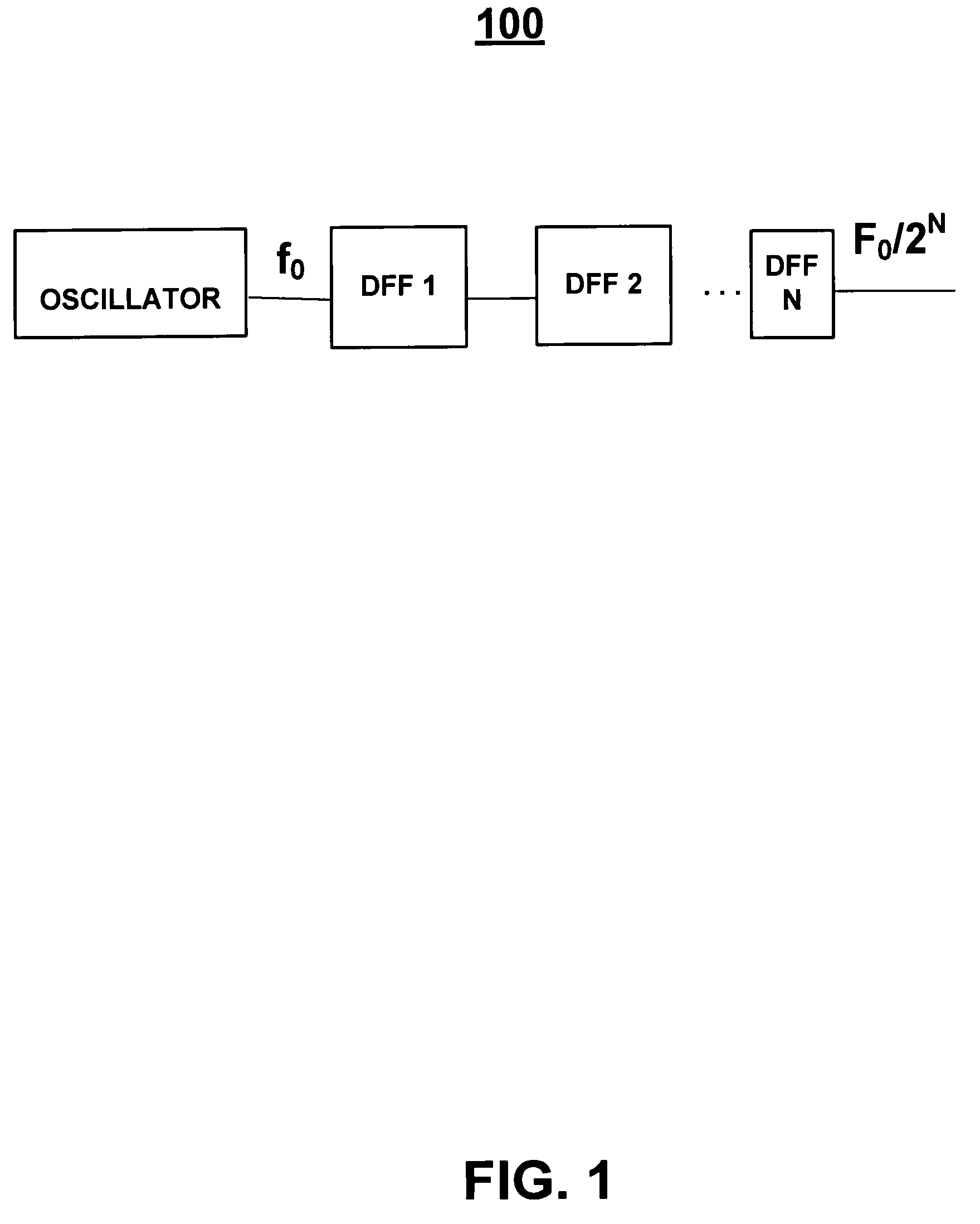
TECHNICAL FIELD[0001]The present invention pertains to methods and systems for electronic component test time improvement.BACKGROUND ART[0002]Production testing involves the individual testing of large numbers of parts to determine if they function acceptably. Each test that is performed on a part exacts a cost in terms of time expenditure. The time expenditure for each part, or component of a part is multiplied over large numbers of parts and thus can be very expensive.[0003]Production testing of integrated circuits includes the evaluation of several different integrated circuit parts. One such part that must be evaluated is the control circuit timer. Timers are used in the control circuitry of most integrated circuits, e.g., power amplifiers. A conventional timer 100 is shown in FIG. 1. Referring to FIG. 1, timer 100 divides a clock of frequency f0 into a clock of frequency f0 / 2N that is produced at an output of timer 100 in order to generate a delay. Such timers can be used to de...

Claims


Application Information

Patent Timeline
Patent Type & Authority Patents(United States)
IPC IPC(8): H03B1/00H03L7/00
CPCG01R31/3016
Inventor MOK, STEPHANIE Z.SINGH, RAMINDER JIT
Owner NAT SEMICON CORP
Why Eureka
Try Eureka