System and method for assembling optical components

a technology of optical components and optical components, applied in the field of fiber optic systems, can solve the problems of increasing the complexity and cost of the assembly process, not controlling all five degrees of freedom, and suboptimal coupling efficiency, and achieves the effects of reducing the complexity and cost of assembly, high coupling efficiency, and increasing the distance between the laser subassembly and the fiber subassembly

Inactive Publication Date: 2007-11-20
OCLARO NORTH AMERICA
View PDF4 Cites 6 Cited by
  • Summary
  • Abstract
  • Description
  • Claims
  • Application Information

AI Technical Summary

Benefits of technology

[0009]One advantage of the disclosed system and method is that relative angular position between the laser subassembly and the fiber subassembly may be controlled in the Θx and Θy directions. This control along with using a collimated beam (produced by the laser subassembly) enables high coupling efficiency between the laser subassembly and the fiber subassembly without requiring tight transverse tolerances in the individual optical components or the use of bulk lenses for coupling. Allowing relaxed transverse tolerances reduces the complexity and cost of assembly. In addition, using a collimated beam enables the distance between the laser subassembly and the fiber subassembly to be increased, without impairing coupling efficiency, thereby creating space for a free-space propagation path and / or for inserting isolators, filters and the like.

Problems solved by technology

Current assembly techniques do not control all five degrees of freedom.
Such an approach results in a certain amount of angular misalignment between the fiber and laser subassemblies, leading to sub-optimal coupling efficiency.
Requiring tight tolerances substantially increases the complexity and cost of the assembly process.
Another drawback of current assembly techniques is that the distance between the fiber and laser subassemblies is purposefully kept short to reduce the amount of angular misalignment between the subassemblies.
The short distance limits the usefulness of the resulting assembly because there is no free-space propagation path.
Further, the short distance precludes inserting isolators, filters and the like between the fiber and laser subassemblies, further limiting the usefulness of the resulting assembly.
However, using coupling lenses also results in complex and costly assembly.

Method used


Image

  • System and method for assembling optical components
  • System and method for assembling optical components
  • System and method for assembling optical components

Examples


Embodiment Construction

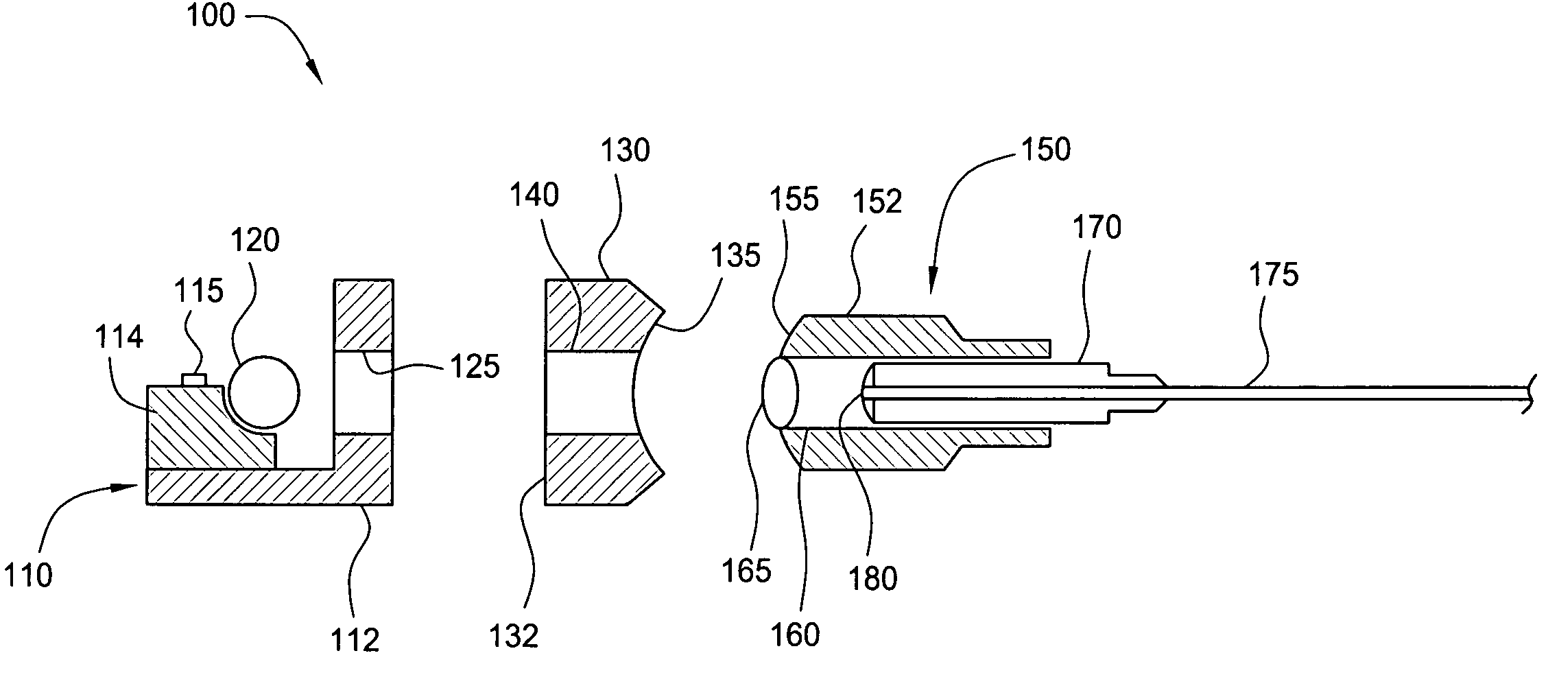
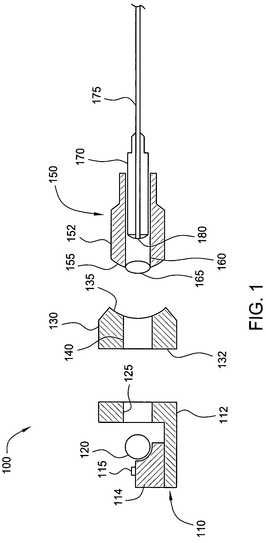
[0018]FIG. 1 illustrates a set of fiber optic components 100 that may be assembled in accordance with the principles of the present invention. As shown, set of fiber optic components 100 includes, without limitation, a laser subassembly 110, an intermediate piece 130 and a fiber subassembly 150. Laser subassembly 110 includes, without limitation, an L-shaped base 112, upon which an optical source 114 is mounted, and a collimating lens 120. Optical source 114 includes a laser 115, which is configured to emit a source beam that passes through collimating lens 120. As described in further detail herein, collimating lens 120 enlarges the diameter of the source beam to produce a collimated beam that enlarges transverse tolerances while ensuring good optical coupling between laser subassembly 110 and fiber subassembly 150. L-shaped base 112 contains an aperture 125 that allows the collimated beam to pass through L-shaped base 112 unimpeded.

[0019]Intermediate part 130 is a cylindrically-sh...


PUM


Abstract

The proposed solution to the problems associated with assembling optical components introduces an angular alignment step and the use of collimated optical beams to the assembly process. One embodiment of a method for aligning optical components includes the steps of angularly aligning a fiber subassembly and a laser subassembly to achieve a desired angular position of the fiber subassembly relative to the laser subassembly, transversely aligning the fiber subassembly and the laser subassembly to achieve a desired linear position of the fiber subassembly relative to the laser subassembly, while maintaining the desired angular position, and installing an intermediate part configured to accommodate the desired angular position and the desired linear position. The method also includes the step of permanently assembling the fiber subassembly, the laser subassembly and the intermediate part, while maintaining the desired angular position and the desired linear position.

Description

BACKGROUND OF THE INVENTION[0001]1. Field of the Invention[0002]This invention relates generally to fiber optic systems and more particularly to a system and method for assembling optical components.[0003]2. Description of the Background Art[0004]An optical transmission system includes a number of optic components, such as a laser subassembly that contains the optical source (i.e., the laser) and a fiber subassembly that includes a portion of the fiber optic cable, that are coupled together to transmit the optical signal. Certain applications, such as pump modules, require high coupling efficiency between the fiber subassembly and the laser subassembly. To optimize coupling efficiency between these components, five degrees of freedom ideally should be controlled during the assembly process. These five degrees of freedom include of the relative linear positions of the fiber and laser subassemblies in the x, y and z directions (where the z-axis is defined to be the optical axis) and t...

Claims


Application Information

Patent Timeline
Patent Type & Authority Patents(United States)
IPC IPC(8): G01B11/26
CPCG01B11/272G02B6/4225G02B6/4221
Inventor BIET, MICHELUGHETTO, GILLESLIEVRE, LAURENTFELSEMBERG, JEROME
Owner OCLARO NORTH AMERICA
Why Eureka
Try Eureka