
Rotary electromagnetic launch tube

a launch tube and electromagnetic technology, applied in the field of underwater launch, can solve the problems of increasing the complexity and cost of the submarine, the loud and environmentally hazardous use of gas generators, and the torpedo room of the submarine one of the most complicated and expensive aspects of submarine design and construction,

Inactive Publication Date: 2005-02-15
THE UNITED STATES OF AMERICA AS REPRESENTED BY THE SECRETARY OF THE NAVY
View PDF9 Cites 32 Cited by
  • Summary
  • Abstract
  • Description
  • Claims
  • Application Information

AI Technical Summary

Benefits of technology

Accordingly, it is an object of the present invention to provide a launch system that can be used to effect both a horizontal and vertical launch from a submarine.
Another object of the present invention is to provide an underwater launch system that reduces the complexity and cost associated therewith by minimizing the size of any pressure hull penetrations used in the construction of the launch system.
Still another object of the present invention is to provide an underwater launch system having a controllable source of launch impulse power so that a minimum launch impulse energy is used, thereby minimizing the acoustic signature associated with a launch.

Problems solved by technology

Due to the inherent risk associated with such large pressure hull penetrations, a submarine's torpedo room is one of the most complicated and expensive aspects of submarine design and construction.
However, the use of such gas generators is loud and environmentally hazardous.
Further, since the horizontal and vertical launch systems operate using different systems / principles, the overall complexity and cost of a submarine is increased when both types of launching must be accommodated in a single vessel.

Method used


Image

  • Rotary electromagnetic launch tube
  • Rotary electromagnetic launch tube

Examples


Embodiment Construction

)

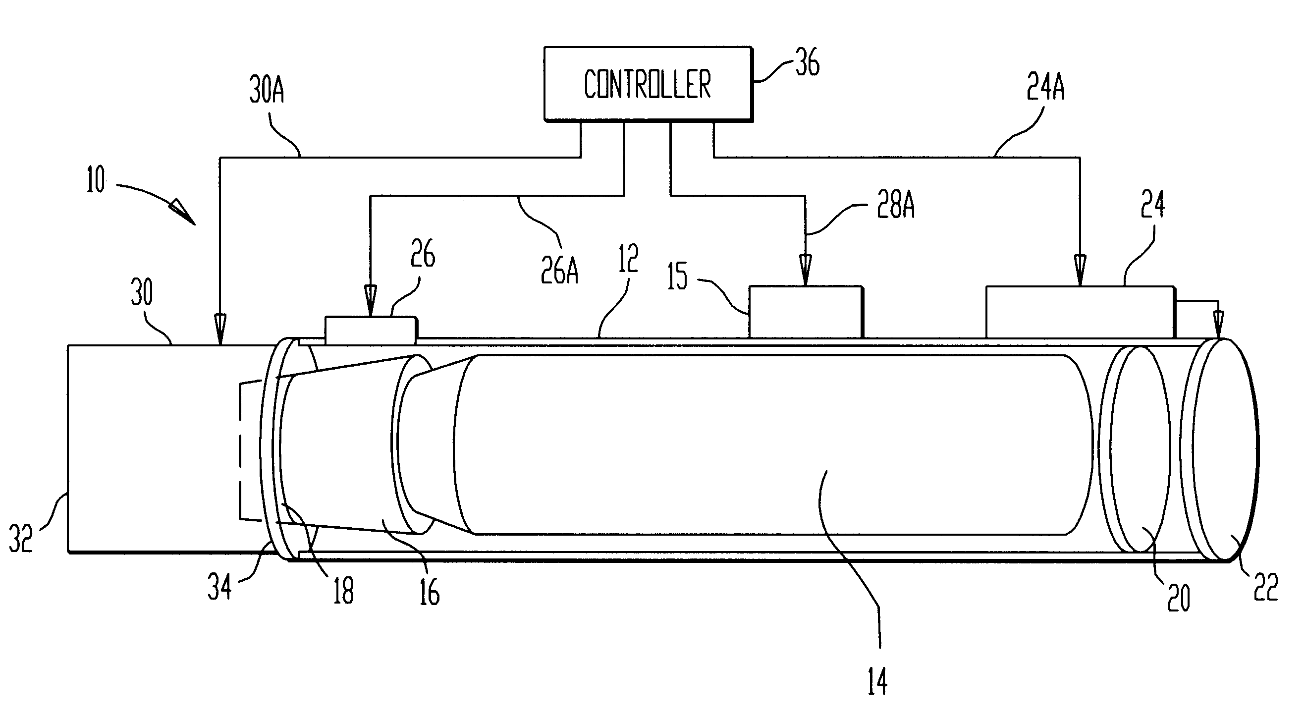
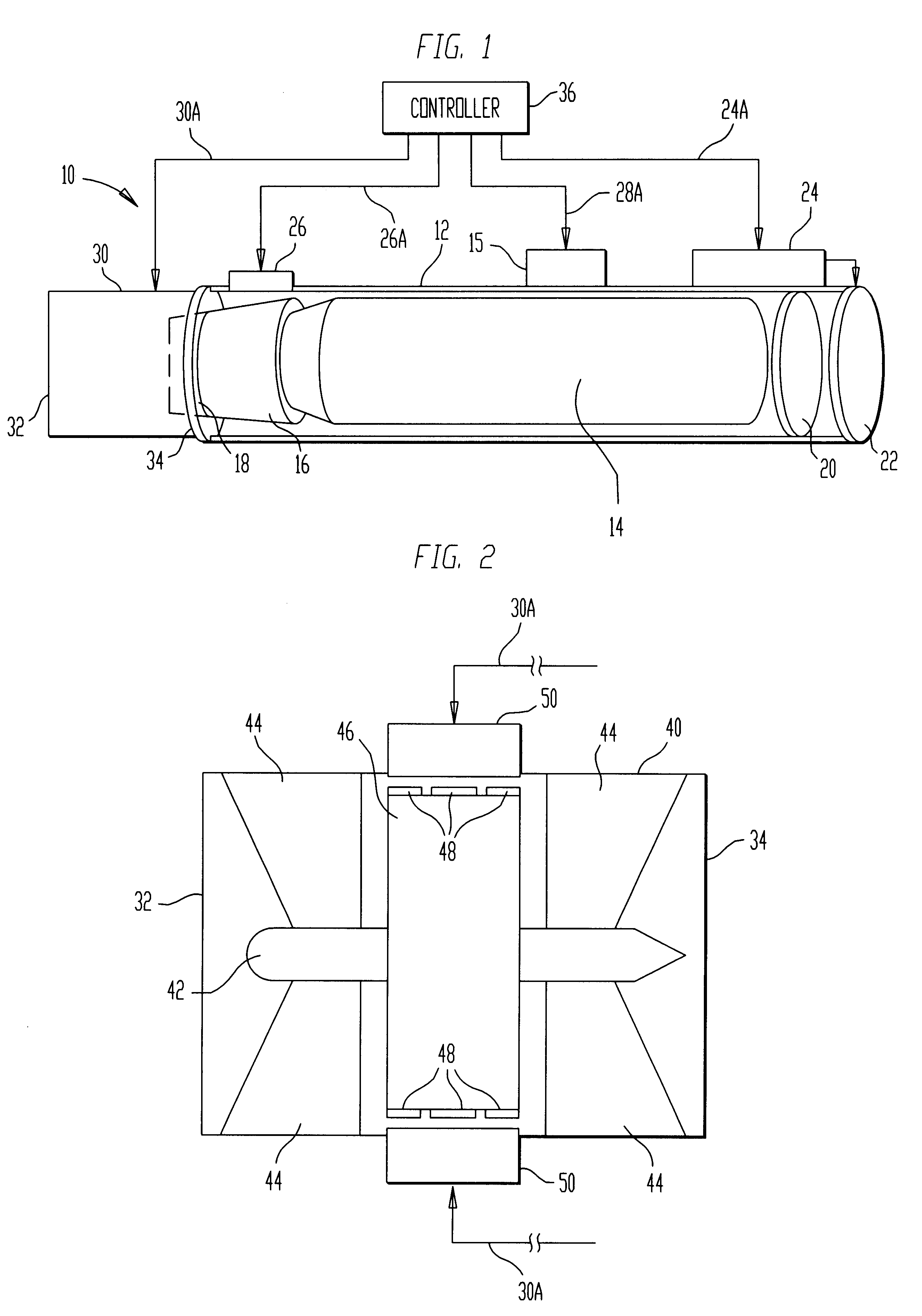
Referring now to the drawings, and more particularly to FIG. 1, a self-contained underwater launch system according to the present invention is shown and referenced generally by numeral 10. Launch system 10 is designed to be used externally with respect to a submarine's pressure hull in either a horizontal or vertical orientation. The particular payload launched by system 10 and / or its support platform (e.g., ship, submarine, buoy, etc.) are not limitations of the present invention.

Launch system 10 has a launch capsule or tube 12 housing a payload 14 therein which can have a propulsor 16 coupled to its aft end. Payload 14 is any payload that is to be launched into a surrounding water environment where it will then run its entire course or transition into the air for airborne travel. Prior to launch time, payload 14 is held in place by an axial restraining lock or stopbolt 15, a variety of which are well known in the art. As shown here, stopbolt 15 is operated by an electrical actua...


PUM


Abstract

An underwater launch system includes a launch tube frangibly sealed at its forward end. At launch time, pressure equalization means introduces water at depth pressure into the launch tube between its frangibly sealed ends. A rotary electromagnetic pump coupled to the launch tube receives water at depth and expels the water at a higher pressure. The higher pressure water is coupled to the aft end of the launch tube.

Description

BACKGROUND OF THE INVENTION(1) Field of the InventionThe present invention relates generally to underwater launching, and more particularly to a self-contained underwater launch system that uses a rotary electromagnetic pump to provide a launch impulse.(2) Description of the Prior ArtA submarine's weapons and other devices are currently launched underwater by one of a horizontal or vertical launch system. The horizontal launch system is used to launch a payload (e.g., torpedo, sonobuoy, unmanned underwater vehicle, mines, etc.) into the water whereas a vertical launch system is used to launch a payload (e.g., missile, signaling device, etc.) into the air. The horizontal launch system typically consists of horizontally positioned pairs of tubes with each pair being connected by an impulse tank structure that directs water flow from an ejection pump to each of the tubes. The aft end of each tube is located in the submarine's torpedo room which is inside the submarine's pressure hull. ...

Claims


Application Information

Patent Timeline
Patent Type & Authority Patents(United States)
IPC IPC(8): B63G8/32B63G8/00F41F3/07F41F3/10F41F3/00
CPCB63G8/32F41F3/10F41F3/07
Inventor GALLIANO, CARLOS E.
Owner THE UNITED STATES OF AMERICA AS REPRESENTED BY THE SECRETARY OF THE NAVY
Learn More