Dynamic path routing with service level guarantees in optical networks

Inactive Publication Date: 2007-11-20
LUCENT TECH INC
View PDF7 Cites 23 Cited by
  • Summary
  • Abstract
  • Description
  • Claims
  • Application Information

AI Technical Summary

Benefits of technology

[0008]In accordance with embodiments of the present invention, a network employs integrated, dynamic routing (IDR) of service level (e.g., bandwidth) guaranteed paths for network tunnel paths (NTPs), such as Internet Protocol (IP) packet connections, through an optical network, such as a wavelength division multiplex (WDM) optical network. For example, IDR accounts for both optical network topology (e.g., optical switches and crossconnects as well as the links between nodes) and resource usage information (e.g., the available/provisioned link bandwidth and available/used wavelength paths). IDR determines several aspects of routing for an arriving request for a network tunnel path (e.g., a request to set up a new packet connection). First, IDR d

Problems solved by technology

However, for wavelength routing, optical network node elements may have different types of wavelength conversion (e.g., optical swit

Method used


Image

  • Dynamic path routing with service level guarantees in optical networks
  • Dynamic path routing with service level guarantees in optical networks
  • Dynamic path routing with service level guarantees in optical networks

Examples


Embodiment Construction

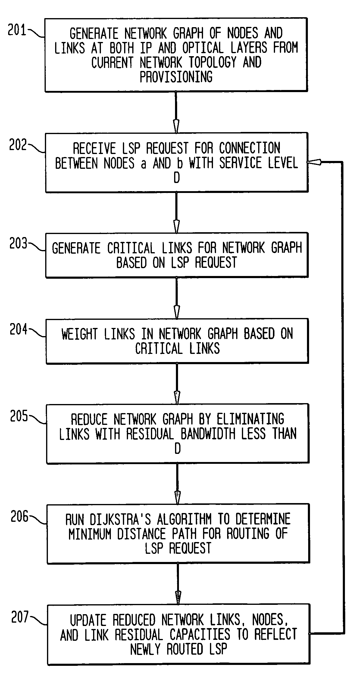
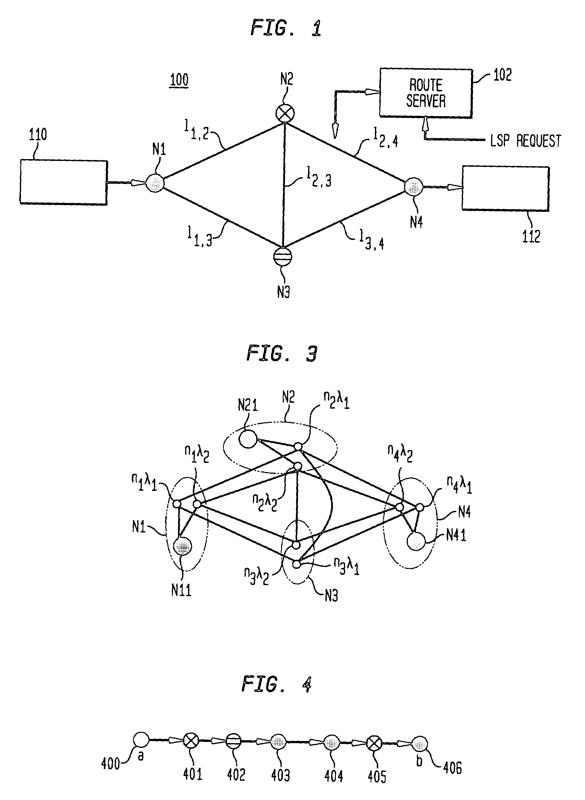
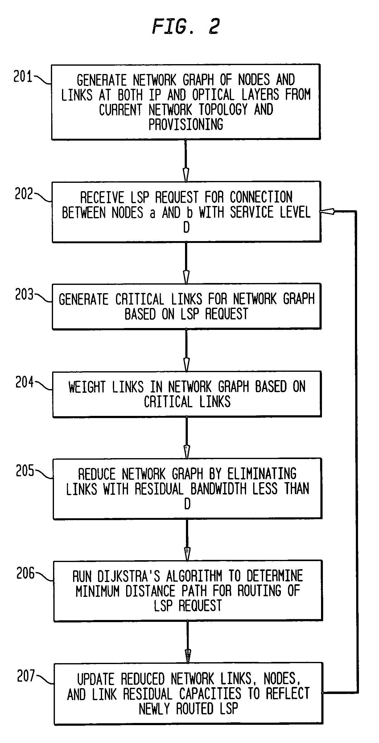
[0020]Embodiments of the present invention employ an integrated, dynamic routing (IDR) method for routing of bandwidth guaranteed network tunnel path (NTP) in optical networks. In accordance with embodiments of the present invention, IDR accounts for the combined knowledge of resource and topology information in both the packet and optical network layers. IDR employs modeling of network elements at both the IP and optical layer to generate a reduced network graph. Based on the demand of a request for the path, the reduced network graph is modified to account for interference to routing of the demand to future requests. A shortest path routing algorithm is then used to compute the path within the modified and reduced graph.

[0021]The exemplary embodiments herein describe IDR for routing IP layer label switched path (LSP) requests in multi-protocol label switched (MPLS) packet networks that are carried over wavelength division multiplex (WDM) optical networks. However, as would be appa...


PUM


Abstract

A scheme for guaranteeing network tunnel path (NTP). e.g., Internet Protocol (IP), service levels in optical (e.g., wavelength-division multiplex (WDM)) networks. The invention, in one embodiment, accounts for both network topology (e.g. switches, cross-connects, and links between nodes) and resource usage (e.g., available/provisioned link bandwidth and available/used wavelength paths), which information may be available from the IP and optical WDM protocol layers, in particular (i) router capacities and (ii) presence or absence of wavelength conversion capability of optical cross-connect at each node. A determination is made whether to route an arriving request for an NTP over existing topology by computing “good” routes in accordance with a defined metric, or to open a new, available optical wavelength path by provisioning nodes of the topology for, and computing “good” routes for new wavelength paths. As many requests as possible are identified without a priori information of future requests.

Description

CROSS-REFERENCE TO RELATED APPLICATIONS[0001]This application claims the benefit of the filing date of U.S. provisional application no. 60 / 2 16,430, filed on Jul. 6, 2000BACKGROUND OF THE INVENTION[0002]1. Field of the Invention[0003]The present invention relates to path routing of packets with service level guarantees in an optical telecommunication network.[0004]2. Description of the Related Art[0005]Packet networks establish new paths through a given network topology, sometimes termed network tunnel paths (NTPs). New paths are established by implementing a routing algorithm when a packet connection request for the path arrives at the network (an NTP request). The NTP request generally specifies a source, which is the node or router of the network that receives the packets for the connection from an external entity (also termed the “origination” or “ingress” node / router). The NTP request also specifies at least one destination, which is the node or router of the network that ultim...

Claims


Application Information

Patent Timeline
IPC IPC(8): G01R31/08H04J14/02H04L12/56H04Q11/00
CPCH04L45/62H04J14/0241H04Q11/0062H04J14/0227H04J14/0284H04Q11/0066H04Q2011/0073H04Q2011/0086
Inventor KODIALAM, MURALIDHARAN S.LAKSHMAN, TIRUNELL V.
Owner LUCENT TECH INC
Why Eureka
Try Eureka