System and method for dynamically determining notification behavior of a monitoring system in a network environment

a monitoring system and network environment technology, applied in error detection/correction, multi-programming arrangements, instruments, etc., can solve the problems of overabundance of notifications, slow network conducting notifications, and may require a large amount of bandwidth, so as to prevent information overload

Inactive Publication Date: 2007-11-20
MOBITV
View PDF15 Cites 5 Cited by
  • Summary
  • Abstract
  • Description
  • Claims
  • Application Information

AI Technical Summary

Benefits of technology

[0016]Embodiments of the present invention provide advantages over prior art notification systems by allowing the notification characteristics of multiple notification modes to be defined. This allows an operator to tune the notification characteristics of embodiments of the present invention to prevent information overload while ensuring that sufficient alarm notifications a

Problems solved by technology

In a large system, this can lead to an overabundance of notifications.
If the software agents send a large number of notifications, the notifications may require a large amount of bandwidth, saturating and slowing the network conducting the notifications.
If, on the other hand, the operator configures the NMS to filter out too many of the received notifications, he or she may never see important notifications, again missing alarm conditions.
This can lead to the software agent communicating a large volume of SNMP traps to the centralized management server.
If the operator chooses to view a large number of the SNMP trap

Method used


Image

  • System and method for dynamically determining notification behavior of a monitoring system in a network environment
  • System and method for dynamically determining notification behavior of a monitoring system in a network environment
  • System and method for dynamically determining notification behavior of a monitoring system in a network environment

Examples


Embodiment Construction

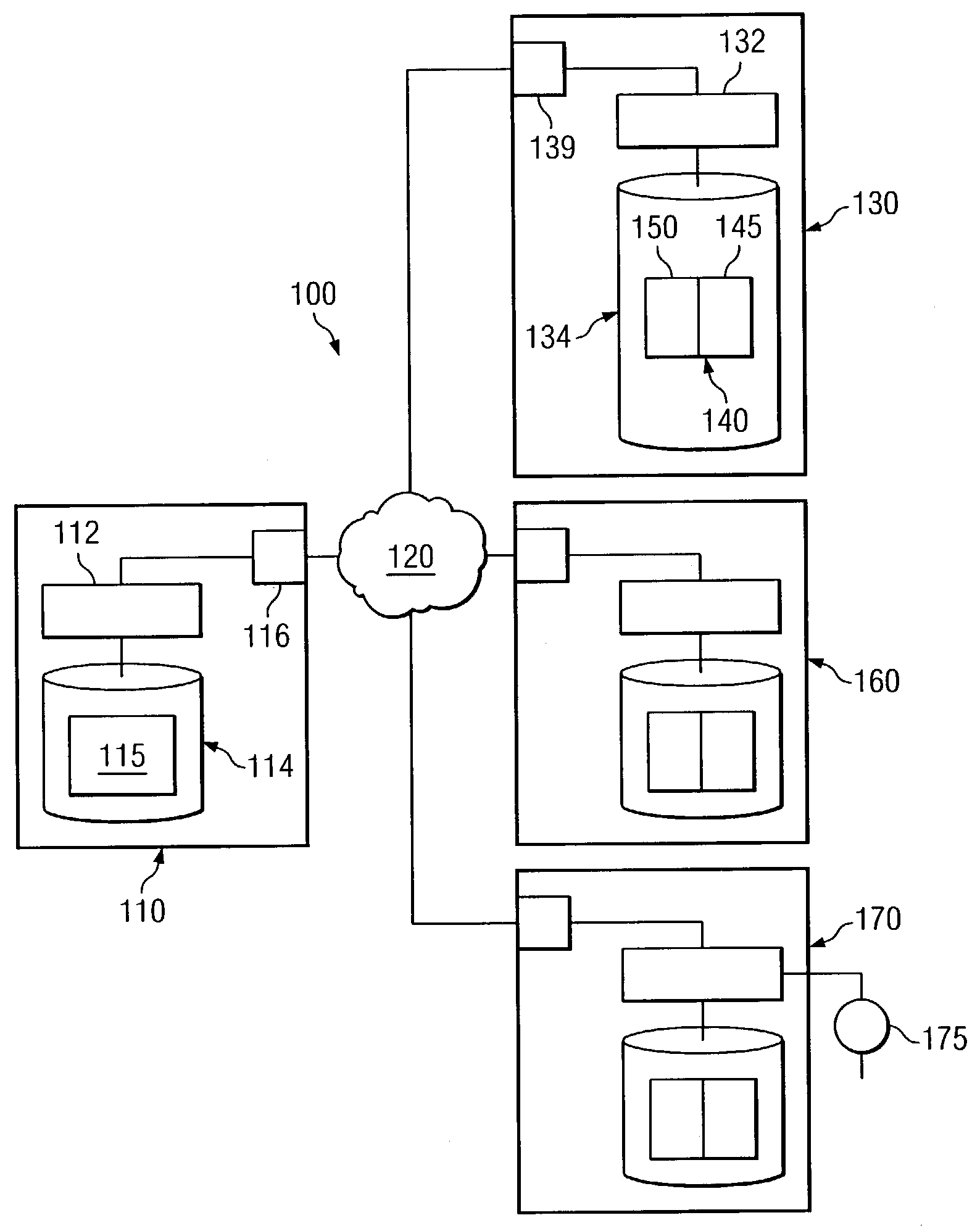
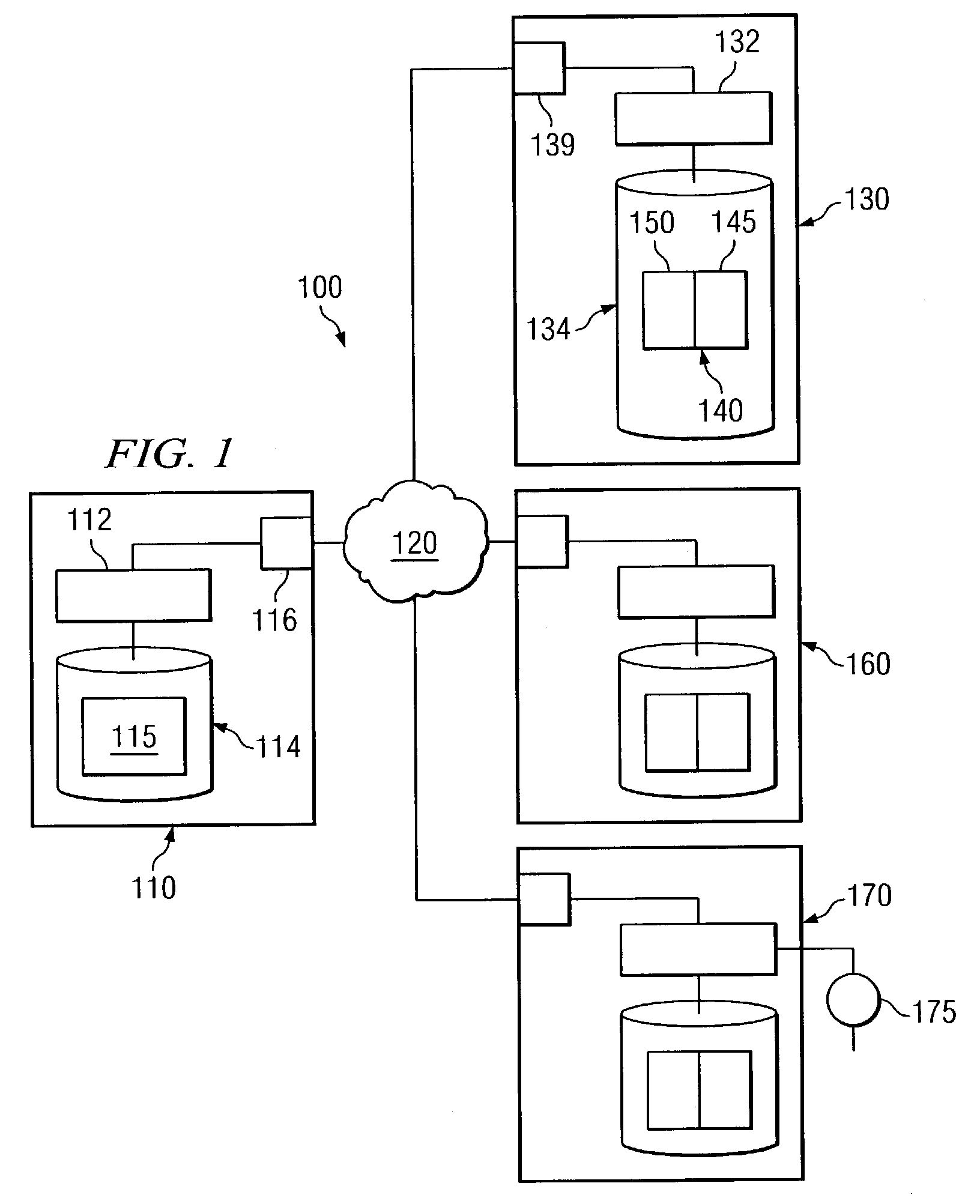
[0022]Preferred embodiments of the present invention are illustrated in the figures, like numerals being used to refer to like and corresponding parts of the various drawings. Embodiments of the present invention provide a system and method to manage the notification behavior of a system. One embodiment of the present invention can define multiple notification modes, each exhibiting different notification behavior, based on the state of a component being monitored. For example, embodiments of the present invention can define notification modes such that notifications that indicate a problem state in a monitored component can be sent out more frequently than notifications that indicate that the monitored component is functioning properly. A number of notification modes can be defined to provide various gradations of notification behavior depending on the state of the monitored component. Moreover, the manner in which a particular notification is sent out can also be controlled. Thus,...


PUM


Abstract

Embodiments of the present invention provide a system and method for dynamically controlling the notification behavior of a system. One embodiment of the present invention can include a system for controlling notification behavior of a system comprising a notification program stored on a computer-readable memory. The notification program can be executable by a computer processor to determine a first notification mode based on a set of configuration parameters and a first-system state. The notification program can be further executable to determine if a notification should be sent out based a set of configuration parameters associated with first notification mode and, if a notification should be sent out, communicate the notification over a network. The notification program can also receive an updated configuration parameter associated with the first notification mode and send out a new notification based on the updated configuration parameter.

Description

CROSS-REFERENCE TO RELATED APPLICATIONS[0001]This application claims priority under 35 U.S.C. § 119(e) to U.S. Provisional Patent Application No. 60 / 348,692, entitled “Mechanism for Dynamically Determining the Notification Behavior of a Complex System,” by de Bonet et al., filed Jan. 15, 2002, U.S. Provisional Patent Application No. 60 / 349,424, entitled “Network Proxy Platform that Simultaneously Supports Data Transformation, Storage, and Manipulation for Multiple Protocols” by de Bonet et al., filed on Jan. 18, 2002, U.S. Provisional Patent Application No. 60 / 349,344 entitled “Modular Plug-In Transaction Processing Architecture” by de Bonet et al., filed Jan. 18, 2002, which are hereby fully incorporated by reference herein. Additionally, U.S. patent application Ser. No. 10 / 342,113, entitled “Method and System of Performing Transactions Using Shared Resources and Different Applications,” by de Bonet et al., filed Jan. 14, 2003 is incorporated by reference herein.TECHNICAL FIELD OF ...

Claims


Application Information

Patent Timeline
IPC IPC(8): G06F3/00G06F9/46
CPCH04L43/10H04L41/0681H04L41/0213G06F11/3006G06F11/3072H04L41/0604H04L41/142
Inventor DE BONET, JEREMY S.STIERS, TODD A.ANNISON, JEFFREY R.
Owner MOBITV
Why Eureka
Try Eureka