Stiffener for stiffening a circuit board

a circuit board and stiffener technology, applied in the direction of electrical apparatus casings/cabinets/drawers, electrical components of non-printed circuits, electrical components association, etc., can solve the problems of connected circuit components being vulnerable to shock and vibration, damage or breakage in service, and flimsy pcbs

Inactive Publication Date: 2005-04-19
SANMINA-SCI CORPORATION
View PDF25 Cites 12 Cited by
  • Summary
  • Abstract
  • Description
  • Claims
  • Application Information

AI Technical Summary

Benefits of technology

[0008]The present disclosure is directed to a stiffener suitable for automated attachment to a PCB and, a method for mechanically attaching the stiffener to the PCB, which substantially reduces or eliminates the disadvantages and problems associated with the manual process of attaching the stiffener described above. One technical advantage of the present invention includes providing a stiffener that is suitable for being quickly and efficiently attached to a PCB during a conventional Surface Mount Technology (SMT) process. The stiffeners of the present invention are suitable for handling by conventional SMT machinery. Another technical advantage of the present invention includes providing a process for automatically attaching the stiffener to the PCB utilizing a conventional SMT process. Utilizing SMT to attach the stiffener to the PCB provides control, consistency, and quality not found in current manual processes, and thus, eliminates or reduces the expense and time associated with current manual processes.
[0009]Additional objects and advantages of the invention are set forth in, or will be apparent to those of ordinary skill in the art from, the detailed description herein. Also, it should be further appreciated that modifications and variations to the specifically illustrated, referenced, and discussed steps, features, materials, or devices hereof may be practiced in various uses and embodiments of this invention without departing from the spirit and scope thereof, by virtue of present reference thereto. Such variations may include, but are not limited to, substitution of equivalent steps, materials, means, or features of those shown, referenced, or discussed, and the functional, operational, or positional reversal of various features, steps, parts, or the like.
[0010]Still further, it is to be understood that different embodiments, as well as different presently preferred embodiments, of this invention may include various combinations or configurations of presently disclosed steps, features, or elements, or their equivalents (including combinations of steps or features or configurations thereof not expressly shown in the figures or stated in the detailed description).

Problems solved by technology

But, one drawback is that, due to its thinness, the PCB is rather flimsy and not structurally stable.
The thinness of the PCB can make the board and it's connected circuit components vulnerable to shock and vibration.
Such shock and vibration can lead to damage or breakage in service or during the mating of the PCB assembly (PCBA) with other PCBAs, other parts of the final assembly, or during the end-use of the product.
Furthermore, conventional soldering processes used during the PCBA manufacturing process provide a source of heat that can soften or warp the PCB, which can cause the soldering to be uneven.
Typically, the stiffeners are mounted or attached to the PCB using conventional mechanical fasteners, such as screws and rivets, via a labor-intensive, manual process.
In some instances, the stiffeners are soldered to the PCB, but, again, using a labor-intensive, manual process.
One drawback of the labor-intensive processes used to manually attach the stiffener to the PCB is the additional cost and time introduced to the PCBA manufacturing process.
Another drawback is the inherent quality problems associated with the manual process.
For example, using screws to attach the stiffener to the PCB introduces problems associated with maintaining proper screw torque.
Excessive torque can damage the PCB while inadequate torque can cause shaking and loss of retention.
These riveting machines typically require manual setup and loading, which can add additional time and, hence, expense to the manufacturing process.
Even using these riveting machines, one still is faced with the problem of insuring that the rivet is not too tight or too loose.

Method used


Image

  • Stiffener for stiffening a circuit board
  • Stiffener for stiffening a circuit board
  • Stiffener for stiffening a circuit board

Examples


Embodiment Construction

[0019]Reference will now be made in detail to presently preferred embodiments of the invention, examples of which are fully represented in the accompanying drawings. Such examples are provided by way of an explanation of the invention, not limitation thereof. In fact, it will be apparent to those skilled in the art that various modifications and variations can be made in the present invention, without departing from the spirit and scope thereof. For instance, features illustrated or described as part of one embodiment can be used on another embodiment to yield a still further embodiment. Still further, variations in selection of materials and / or characteristics may be practiced, to satisfy particular desired user criteria. Thus, it is intended that the present invention cover such modifications and variations as come within the scope of the present features and their equivalents.

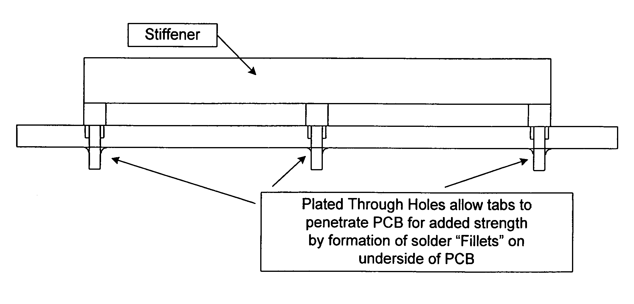
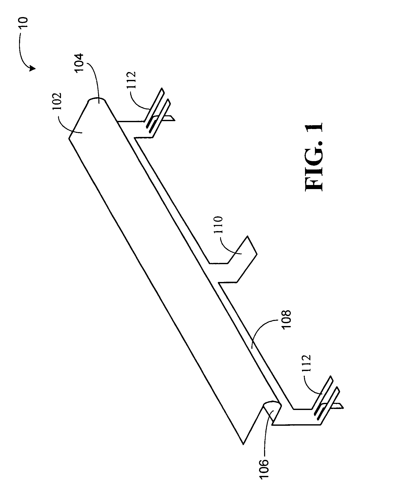
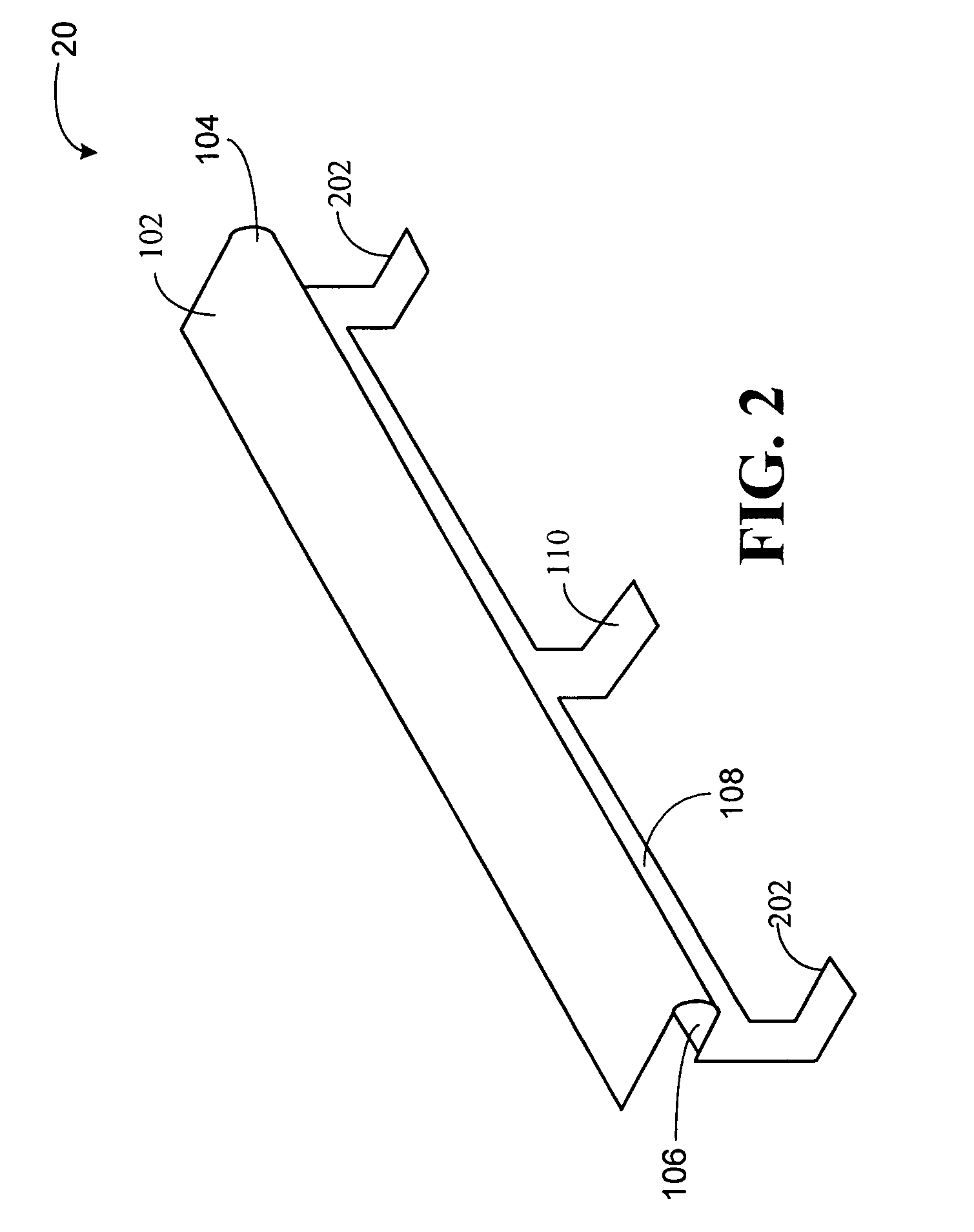
[0020]The present invention provides a printed circuit board (PCB) stiffener for overcoming the inherent ...


PUM

PropertyMeasurementUnit
heightaaaaaaaaaa
lengthaaaaaaaaaa
areaaaaaaaaaaa

Abstract

A printed circuit board stiffener is provided comprising a generally U-shaped elongated horizontal assembly having a substantially horizontal surface, an elongated vertical member extending downward from and rigidly coupled to one of the elongated horizontal assembly members opposite the assembly's curved edge and having a plurality of legs extending from the elongated vertical member, each such leg further comprising a flange extending substantially perpendicular to its respective plurality of legs in a direction toward the elongated horizontal assembly's curved edge. Each of said flanges are suitable for attachment to a surface of a circuit board. Further, such stiffener is capable of being moved, oriented, placed and mechanically bonded to the printed circuit board using existing SMT robotic assemblies.

Description

BACKGROUND[0001]1. Field of the Invention[0002]The present invention relates generally to mechanical devices useful to strengthen circuit boards and, more specifically, to a circuit board stiffener that can be applied utilizing Surface Mount Technology (SMT).[0003]2. Description of the Related Art[0004]Printed circuit boards (PCBs) are well known in the art. PCBs are typically very thin and made of layers of glass fabrics or fibers that are bonded together by resins. The thinness of a PCB provides an advantage in that the PCB does not consume much space. But, one drawback is that, due to its thinness, the PCB is rather flimsy and not structurally stable. The thinness of the PCB can make the board and it's connected circuit components vulnerable to shock and vibration. Such shock and vibration can lead to damage or breakage in service or during the mating of the PCB assembly (PCBA) with other PCBAs, other parts of the final assembly, or during the end-use of the product. Furthermore,...

Claims


Application Information

Patent Timeline
Patent Type & Authority Patents(United States)
IPC IPC(8): H05K1/02H05K1/18H05K7/14
CPCH05K1/0271H05K7/1461H05K1/181H05K2201/2009Y10T29/49155Y10T29/4995Y10T428/12201Y10T29/53174Y10T29/49144Y10T29/49815
Inventor IRELAND, JOHN A.
Owner SANMINA-SCI CORPORATION
Why Eureka
Try Eureka