Aerating decanter with dispensing valve

a technology of aerating decanters and valves, which is applied in the direction of liquid handling, liquid transfer devices, transportation and packaging, etc., can solve the problems that none of these vessels dispense wine from the vessel into the glass, and no such devices

Active Publication Date: 2007-11-27
COOPERS HAWK INTERMEDIATE HLDG LLC
View PDF11 Cites 44 Cited by
  • Summary
  • Abstract
  • Description
  • Claims
  • Application Information

AI Technical Summary

Benefits of technology

[0004]The invention provides the consumer a means to aerate wine, trap particulates that may have formed in the bottle during fermentation or those introduced during the process of uncorking the a bottle of wine, and dispense wine into a suitable receptacle.
[0006]Once the valve is secured to the opening, the glass decanter is positioned on the structural support and secured in place. A fine stainless steel mesh filter is positioned at the mouth of the decanter and allowed to rest on the indention ring that secures the decanter to the structure. Once the filter is in place, the glass sphere is placed on the concave shape of the filter. Water inside the sphere provides the necessary weight to keep the sphere stationary while pouring wine over its surface.
[0009]In the event white wines are preferred, the glass sphere may be frozen to assist in the preservation of cooler wine temperatures. A previous patent was secured for this function in 1903 by August Glebsattel, (U.S. Pat. No. 740,847) although the intent was primarily for health purposes. The cooling is accomplished by 3 avenues. First, as wine passes over the surface of the sphere, the wine is cooled without diluting its contents with water. Second, once a full bottle is poured into the decanter, the level of the wine from a full bottle fully contacts the sphere and chills the wine. Third, once some of the wine is dispensed, the stainless steel filter can be removed and the sphere positioned on the indention ring. This provides a mechanical seal impeding the flow of air to the surface of the wine and provides cool air for the top half of the decanter.

Problems solved by technology

None of these vessels dispense wine from the vessel into their glass without pouring.
Although each of the aforementioned methods serve the purpose of aerating wine, at present there are not any such devices that provide the aeration process coupled with a filtering device where a consumer can serve themself without pouring from a container.

Method used


Image

  • Aerating decanter with dispensing valve
  • Aerating decanter with dispensing valve
  • Aerating decanter with dispensing valve

Examples


Embodiment Construction

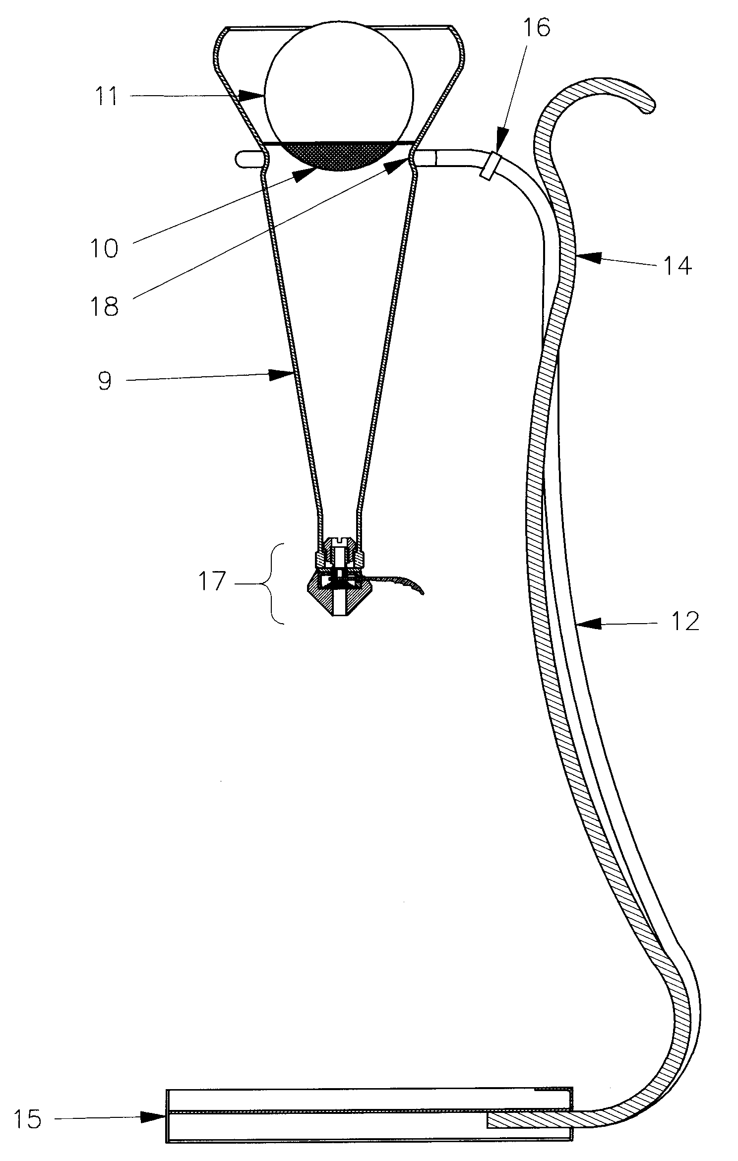
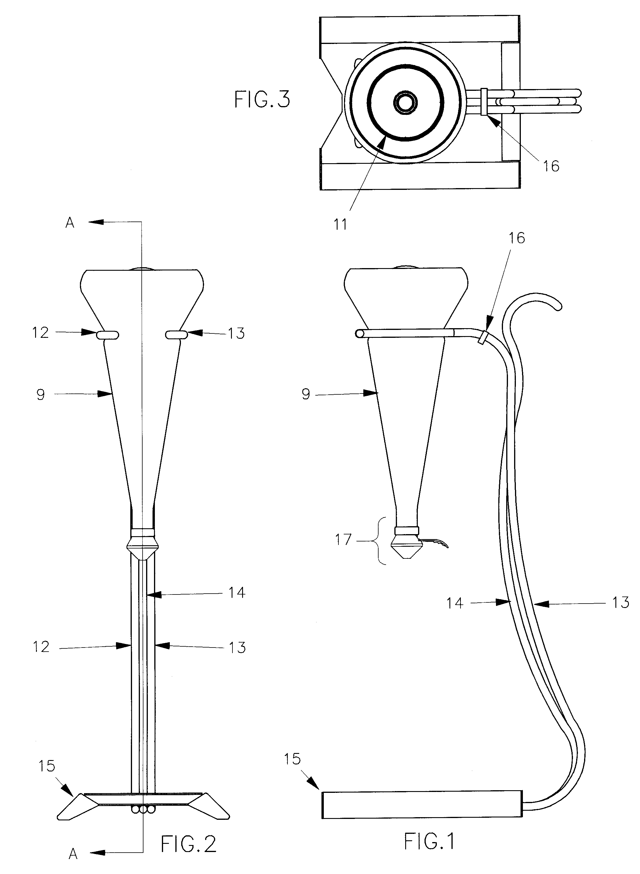
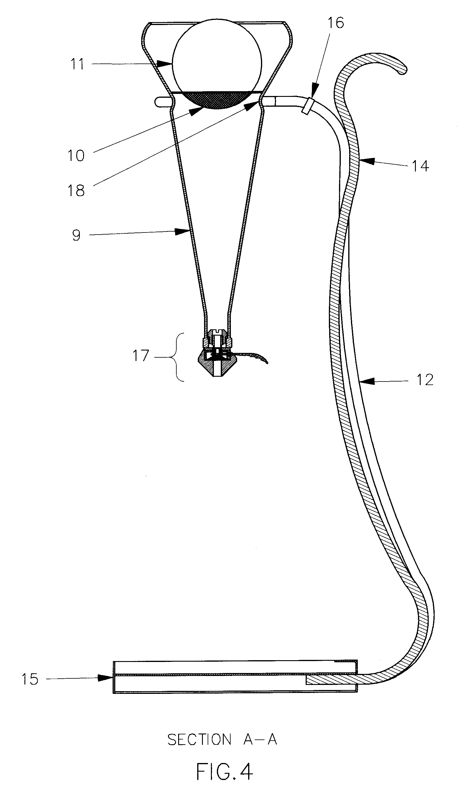
[0016]The described invention provides an artistic mechanism to aerate, filter, chill and store wine for easy dispensing into a wine glass. The basic components of the invention are described as a decanter (9) which houses the nozzle (17), filter (10), and wine bubble (11). The decanter (9) is mechanically attached to the right (13) and left (12) hand support rods. These rods as well as the center decorative rod (14) are welded or otherwise attached to the base (15). A clip (16) bridges the right (13) and left (12) hand supports to squeeze the rods against the decanter (9) at the indention ring (18) (FIG. 4). This holds the decanter (9) firmly in the support structure. When the clip (16) is removed the decanter (9) can then be removed from the support structure for cleaning.

[0017]The valve (17) which dispenses wine is a spring (8) loaded devise which is activated by physically rotating the lever (6) upward in order to pivot the lever (6) away from the grommet (5). The valve chamber ...


PUM

PropertyMeasurementUnit
concave shapeaaaaaaaaaa
weightaaaaaaaaaa
temperaturesaaaaaaaaaa

Abstract

This invention combines several processes into on easy to use product. The glass sphere dramatically enhances the aeration procedure by gently exposing air to thin waves of wine as wine passes over the surface of the sphere. The integrated filter provides a larger surface than normally found in wine filtration devices. The supporting structure secures the decanter in such a way that consumers can easily dispense wine without handling a wine bottle or conventional decanter.

Description

BACKGROUND OF INVENTION[0001]At present there are a variety of methods a consumer can use to aerate wines. These processes range from manual to highly mechanized methods. Manually, wine is poured into a vessel, which exposes the wine to the air as it is transferred from the bottle. There are many artistic decanters on the market to accomplish this task ranging from pitchers to highly crafted crystal containers. Some specialty devices have been created to assist in aerating wine introduced into decanters which regulate the flow of wine into the decanter (U.S. Pat. No. 5,293,912). None of these vessels dispense wine from the vessel into their glass without pouring. Mechanically, there are apparatuses that; inject air into the wine bottle, (U.S. Pat. Nos. 4,494,452 4,785,724 5,595,104 6,508,163); transfer wine back and forth between decanters (U.S. Pat. No. 4,162,129); as well as swirling the wine with a magnetic motor driven oscillator (U.S. Pat. No. 6,332,706).[0002]Although each of ...

Claims


Application Information

Patent Timeline
Patent Type & Authority Patents(United States)
IPC IPC(8): B65B39/00B01F3/04B01F5/06B67D7/80
CPCB01F3/04475B01F5/0693B01F5/0682B01F2215/0072B01F23/23211B01F25/4523B01F25/45B01F2101/17
Inventor MOORE, JAMES R.
Owner COOPERS HAWK INTERMEDIATE HLDG LLC
Why Eureka
Try Eureka