Mini desktop stapler

a stapler and desktop technology, applied in the field of spring-actuated staplers, can solve the problems of not disclosed a functional mechanism for resetting the striker, no linkage is described to enable a reset spring to lift the striker against the force of the power spring, and it is difficult or uncomfortable for users to apply or squeeze such force with only their thumbs, etc., to achieve maximize the effective handle length and useful leverage

Active Publication Date: 2007-11-27
WORKTOOLS
View PDF59 Cites 46 Cited by
  • Summary
  • Abstract
  • Description
  • Claims
  • Application Information

AI Technical Summary

Benefits of technology

[0009]In a preferred embodiment of the present invention, the stapler is short lengthwise and minimally tall yet still substantially fits the internal spring-powered action and the necessary handle travel to energize and fire the stapler. The present invention stapler design is preferably a high start type since this is generally more compact vertically as compared to a low start type. With a small size, the spring powered stapler of the present invention is comfortable to carry and store. If it is clipped to a backpack, belt or other article that is worn, it will not swing or bang around as a conventionally sized stapler would. It also will easily fit into a typical jacket or pants pocket, or in a purse. The stapler includes a narrow body shape that allows it to hang or store unobtrusively.
[0010]In a preferred embodiment, a spring-actuated mechanism of the present invention fits within a housing body similar in size to conventional direct action staplers having miniature proportions. The power spring stores user applied energy and suddenly releases that energy via accelerating a striker which ejects a staple by impact blow. In a preferred embodiment, the power spring is a flat spring having co-extending resilient arms cantilevered from a common mounting. Such a spring provides an effective stapler function in a short and vertically compact package. The power spring includes an upper position immediately adjacent to a top wall of the housing, and a lowest position against an absorber abutting a staple chamber.
[0012]In a preferred embodiment of the present invention stapler, a handle is pivotably attached to the body. When viewed from the side, the handle may be hinged at a lower rear corner or position of the stapler body while the pressing area is at a diagonally opposite front, top corner. The handle is thus hinged beneficially as far as practical away from the pressing area of the handle. In this way, the effective handle length is maximized within the confines of a miniature stapler. During a pressing stroke, a user's fingers are sufficiently distant from the hinge to provide useful leverage without excessive angle changes of the pressing area.

Problems solved by technology

However, no functional mechanism to reset the striker is disclosed.
Instead, the striker is somehow lifted by a very stiff reset spring, yet no linkage is described to enable a reset spring to lift the striker against the force of the power spring.
Needless to say, it is difficult or uncomfortable for a user to apply or squeeze with such force using only a thumb.

Method used


Image

  • Mini desktop stapler
  • Mini desktop stapler
  • Mini desktop stapler

Examples


Embodiment Construction

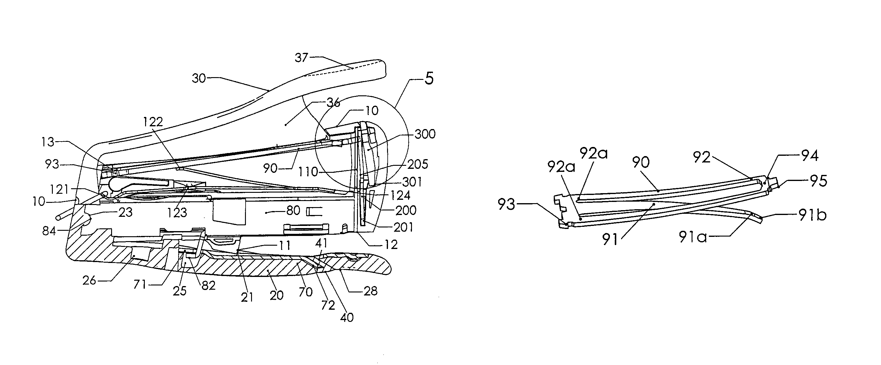
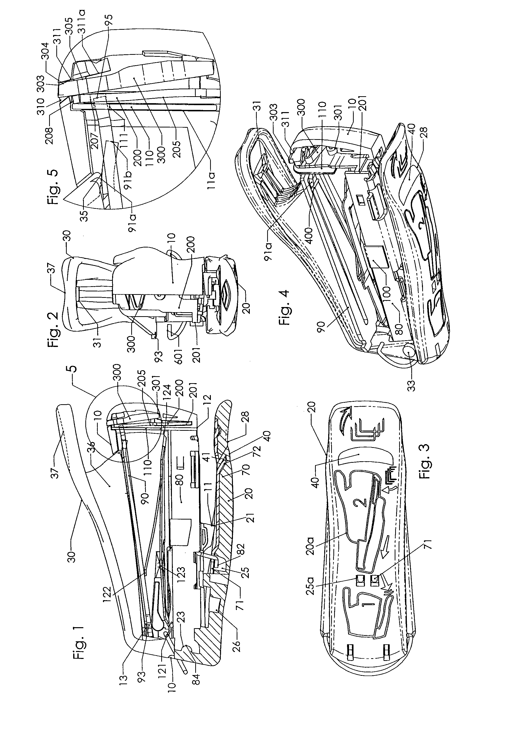
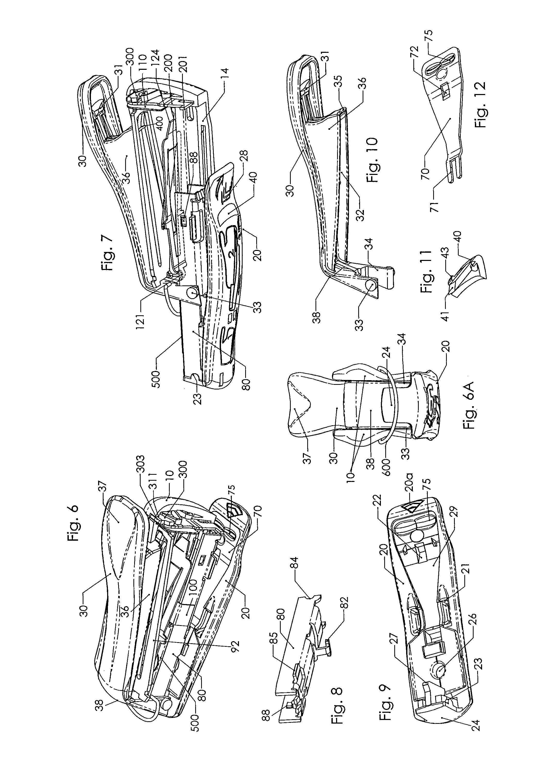
[0052]The present invention in various exemplary embodiments is directed to a spring powered stapler with miniature proportions. Such a miniature spring powered stapler is smaller in overall size and has a smaller staple capacity for convenient portability and low weight yet still functions as a full sized, direct action or spring powered stapler. For example, office workers who travel and perform their tasks en route in an airplane, in a car, at the hotel, or at any locale remote from the home office can use the spring powered miniature stapler for significant paper and like stapling jobs without having to lug around a bulky and heavy desktop stapler. Realtors, school teachers, students, sales reps, and the like who may work outside of an office environment might not have ready access to a full sized desktop stapler can also enjoy the diminutive, pocket size portability, low weight, and convenient access of the present invention stapler. The present invention stapler is also a valu...


PUM


Abstract

A miniature spring-actuated stapler includes a tapered, flat power spring to store energy and eject staples. The power spring pivots at a rear of the stapler housing and includes three co-extensive arms terminating near the striker. As the L-shaped handle of the stapler is pressed, it acts on the center arm of the power spring to deflect it downward while the outer arms deflect upward. The arms are integral at a rear end and the outer arms are linked to the striker at the front. A tapered, flat reset spring disposed generally parallel to the power spring is used to reset the internal action. The housing includes open top and rear areas with the handle providing the enclosure thereof. A base assembly is slidably attached at a bottom of the stapler with an open position exposing a staple-loading chamber.

Description

FIELD OF THE INVENTION[0001]The present invention relates to spring-actuated staplers for fastening paper. More precisely, the present invention relates to a design for a miniaturized stapler.BACKGROUND OF THE INVENTION[0002]Spring powered staplers and staple guns operate by driving a striker with a power spring. The striker ejects a staple by impact blow. In a desktop stapler, the staple is ejected into an anvil of a normally pivotably attached base. Two general principles for spring-actuated staplers are used. In the first design, the striker has an initial position in front of a staple track. The striker is lifted against the force of the power spring to a position above the staple track. The striker is released to impact and eject the staple. This design may be referred to as a “low start” stapler. A second design uses a “high start” position. That is, the striker has an initial position above the staples loaded on the staple feed track. The power spring is deflected while the l...

Claims


Application Information

Patent Timeline
Patent Type & Authority Patents(United States)
IPC IPC(8): B25C5/06
CPCB25C5/11B25C5/025
Inventor MARKS, JOEL S.
Owner WORKTOOLS
Why Eureka
Try Eureka