Sheet processing apparatus and image forming apparatus having the same

a technology of image forming apparatus and processing apparatus, which is applied in the direction of electrographic process, instruments, transportation and packaging, etc., can solve the problems of inability to align the sheet bundle, inability to stack the sheet bundle in its aligned state, and inability to achieve the gravity fall of the sheet bundle, etc., to achieve simple construction and improve the stackability of the sheet bundle

Active Publication Date: 2007-11-27
COPYER
View PDF35 Cites 20 Cited by
  • Summary
  • Abstract
  • Description
  • Claims
  • Application Information

AI Technical Summary

Benefits of technology

[0024]So, the present invention has been made in view of such circumstances and an object thereof is to provide a sheet processing apparatus which can improve the stackability of sheet by a simple construction, and an image forming apparatus provided with the same.
[0025]An embodiment of the present invention has as its object to provide a sheet processing apparatus which can prevent the positional deviation of a sheet bundle discharged after treated, and an image forming apparatus provided with the same.
[0026]Also, an embodiment of the present invention has as its object to provide a sheet processing apparatus which can stably align the position of a sheet in a sheet conveying direction by a simple construction, and an image forming apparatus provided with the same.

Problems solved by technology

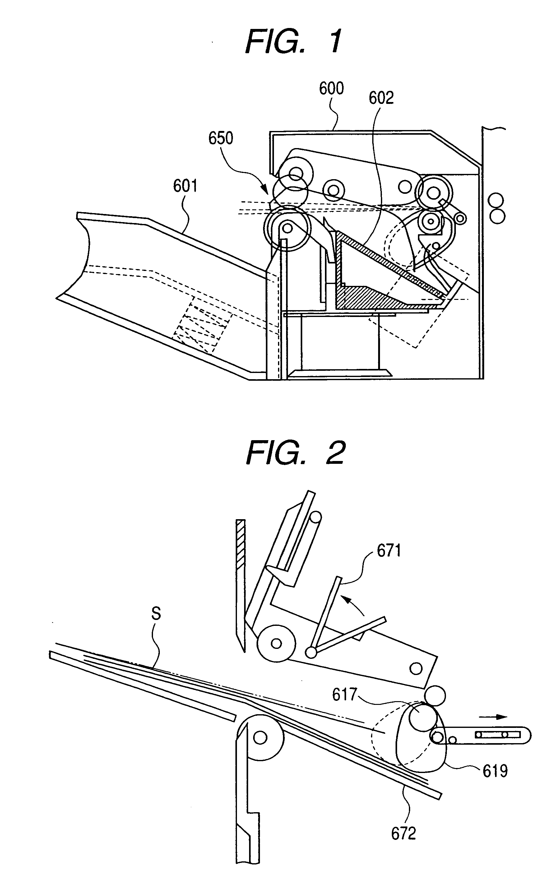
However, in such a conventional sheet processing apparatus and an image forming apparatus provided with the same, when the sheet bundle is to be stacked on the inclined stack tray 601, the sheet bundle can be aligned by the inclination of the stack tray 601, but when the sheet bundle is to be discharged to a substantially horizontal stack tray, the alignment of the sheet bundle by the gravity fall thereof cannot be effected.
Particularly, in the case of an unstapled sheet bundle, the alignment in the sheet bundle is liable to deviate, and once it deviates, it is impossible to align the sheet bundle again.
That is, in a case where the sheet bundle is discharged to the substantially horizontal stack tray, it has been difficult to stack the sheet bundle in its aligned state.
When in order to effect the alignment of the sheet S in the conveying direction thereof, a frictional force obtained by the rotation of the aligning belt is utilized as another means, there has been the possibility that deviation is caused to an aligned sheet bundle by the delicate vibration of the aligning belt occurring during the rotation of the aligning belt.
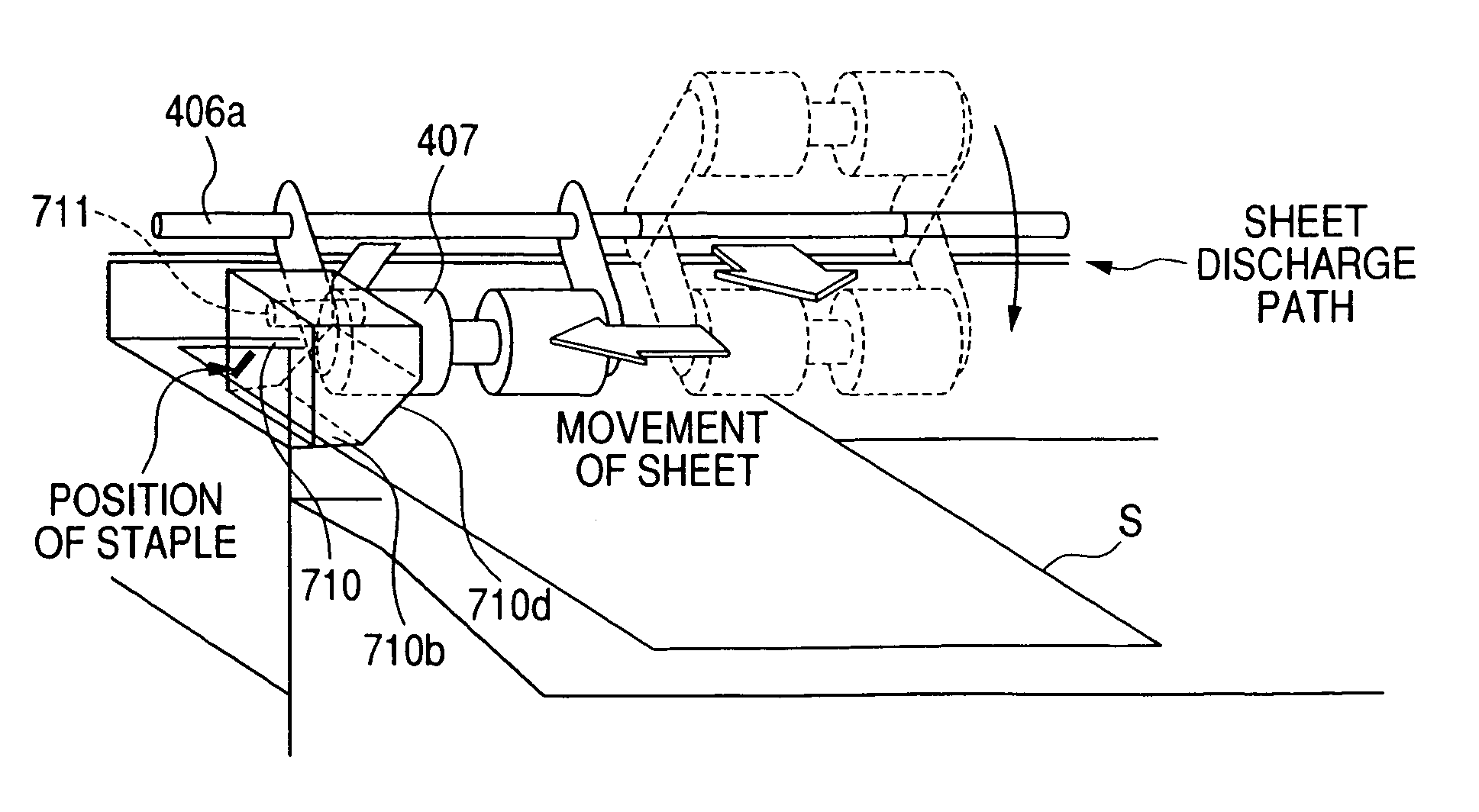
Further, the sheet S is discharged onto the treatment tray by the discharge roller 617 so as to fly and therefore, when the sheet S is discharged onto the treatment tray, the falling position of the sheet is not stable in some cases depending on the kind of the sheet S, and in such cases, it has sometimes been impossible to cause the discharged sheet to stably abut against the aligning and abutting portion.
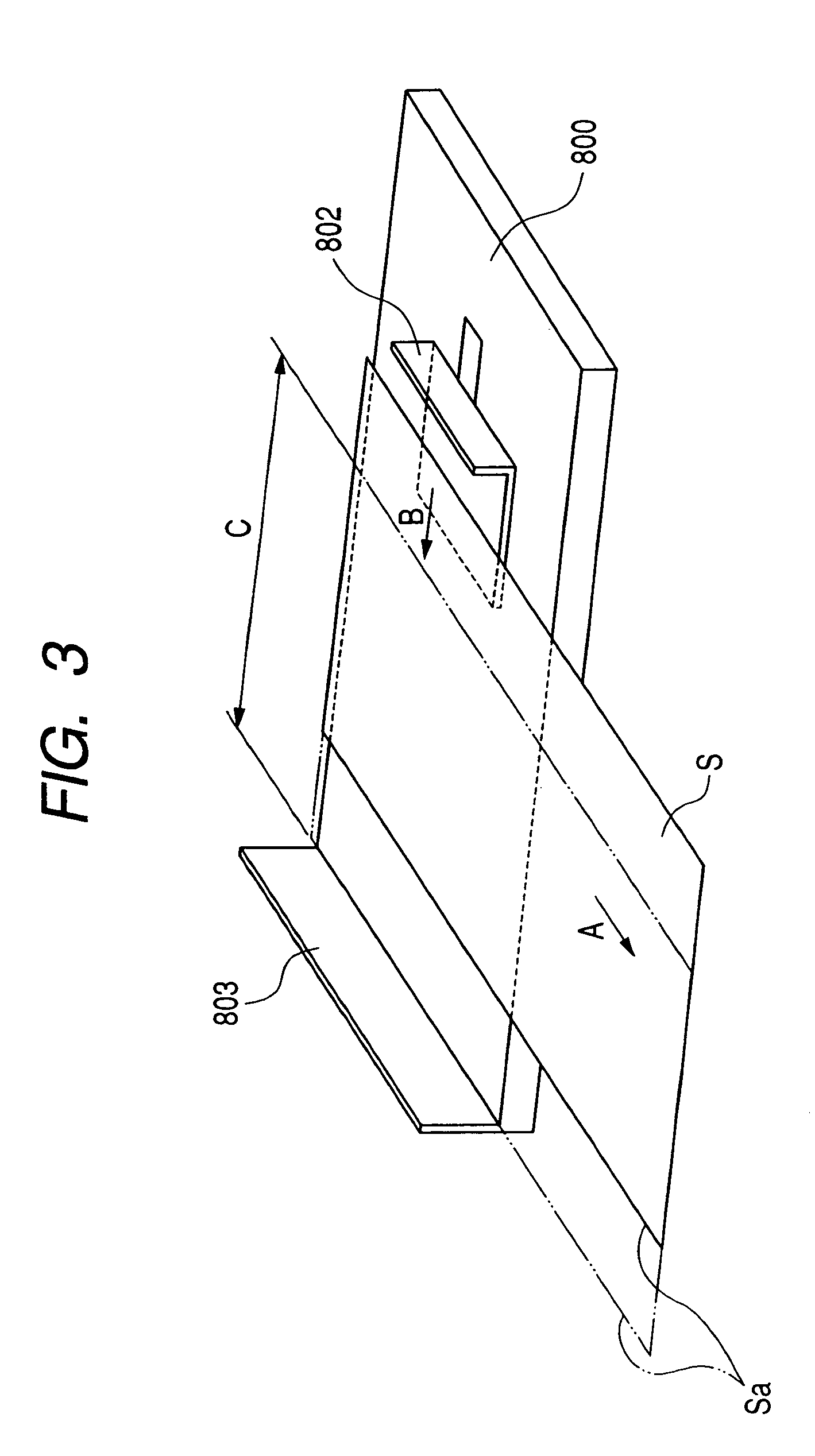
However, in the conventional sheet processing apparatus provided with the width regulating plate 802, the amount of movement of the width regulating plate 802 is determined to about 2 mm to about 3 mm further from the position at which the side edge Sa of the sheet S has been caused to abut against the abutting wall 803, and this has led to the problem that in the case of an upper trough curl in which the opposite side edges of the sheet S face up, or a lower trough curl in which the opposite side edges of the sheet S face down, the width C of the sheet becomes narrower by the amount of curl of the sheet S than the actual width of the sheet, and the sheet cannot be caused to reliably abut against the abutting wall 803 by the predetermined width narrowing amount of the width regulating plate 802, and width aligning accuracy is remarkably lowered.
Also, when the sheet has come into contact with the width regulating plate 802, if the sheet is in an upper trough curled state, the sheet may more or less float up from the treatment tray 800 along the curl, and if conversely the sheet is in a lower trough curled state, the sheet may more or less float up from the treatment tray 800 in such a manner as to be turned up along the curl, and this has led to the problem that the width aligning accuracy is remarkably lowered.
Also, in the conventional sheet processing apparatus, the entire side edge of the sheet is pushed by the width regulating plate 802, and this has also led to the problem that if the size of the sheet during the cutting thereof is uneven, the width aligning accuracy cannot be enhanced.

Method used


Image

  • Sheet processing apparatus and image forming apparatus having the same
  • Sheet processing apparatus and image forming apparatus having the same
  • Sheet processing apparatus and image forming apparatus having the same

Examples


Embodiment Construction

[0068]The preferred embodiments for carrying out the present invention will hereinafter be described in detail with reference to the drawings.

[0069]FIG. 4 is a cross-sectional view showing the constructions of a sheet processing apparatus and an image forming apparatus according to an embodiment of the present invention. In FIG. 4, the image forming apparatus A is provided with an image forming apparatus main body 500 and an automatic document feeder (ADF) 300 provided on the upper surface of the image forming apparatus main body 500. A sheet processing apparatus 400 as a sheet after treatment apparatus for effecting the after treatment of a sheet discharged from the image forming apparatus A of the present invention is mounted externally of the image forming apparatus main body 500.

[0070]The image forming apparatus according to the present invention is not restricted to the image forming apparatus shown in FIG. 4, but may be an image forming apparatus shown in FIG. 5. FIG. 5 is a c...


PUM

PropertyMeasurementUnit
distanceaaaaaaaaaa
width sizeaaaaaaaaaa
degree of distanceaaaaaaaaaa

Abstract

A sheet processing apparatus including a first sheet stacking portion for stacking sheets thereon, a second sheet stacking portion provided downstream of the first sheet stacking portion with respect to a sheet conveying direction, a sheet holding device for holding the sheets stacked on the first sheet stacking portion, and a holding device moving device for moving the sheet holding device between a holding position for holding the sheets and a discharging position provided downstream of the holding position in the sheet conveying direction, wherein the discharging position has a predetermined distance upstream from a stop position in which the sheet holding device moved to a downstream side with respect to the sheet conveying direction by the holding device moving device is stopped to an upstream side.

Description

[0001]This application claims priority benefits of Japanese Patent Application Nos. 2004-122291 filed Apr. 16, 2004, and 2004-122292 filed Apr. 16, 2004, and 2004-122293 filed Apr. 16, 2004, and 2004-123555 filed Apr. 19, 2004, the entire disclosures of which are hereby incorporated herein by reference in their entirety.BACKGROUND OF THE INVENTION[0002]1. Field of the Invention[0003]This invention relates to a sheet processing apparatus and an image forming apparatus provided with the same.[0004]2. Description of the Related Art[0005]Heretofore, some of image forming apparatuses such as a copying machine, a printer, a laser printer and a facsimile, and a compound apparatus of these have been designed such that an image forming apparatus main body is provided with a sheet processing apparatus for effecting such treatment as a stapling treatment on sheets discharged from the image forming apparatus main body.[0006]As such a sheet processing apparatus, there is one designed such that s...

Claims


Application Information

Patent Timeline
Patent Type & Authority Patents(United States)
IPC IPC(8): B65H37/04B65H9/10B65H29/00B65H29/22B65H29/70B65H33/04B65H33/14B65H39/02B65H39/045B65H39/05B65H39/055B65H39/065B65H39/07B65H39/075B65H39/10G03G15/00
CPCB65H9/106B65H29/22B65H31/3027G03G15/6552B65H39/10B65H33/14B65H2301/42262
Inventor SUGIYAMA, AKIHIKOSAEKI, NAOTOKODAMA, TAKEHIKOFUNADA, NAOYASUSUZUKI, HIROSHI
Owner COPYER
Why Eureka
Try Eureka