LED light sources for image projection systems

a technology of led light source and image projection system, which is applied in the direction of lighting elements, lighting and heating apparatus, instruments, etc., can solve the problems of hid lamps that are serious in use, hid bulbs that are difficult to operate,

Inactive Publication Date: 2007-11-27
LIGHTING SCI GROUP
View PDF55 Cites 33 Cited by
  • Summary
  • Abstract
  • Description
  • Claims
  • Application Information

AI Technical Summary

Problems solved by technology

Unfortunately, HID lamps present serious problems in use.
The heat and pressure in HID bulbs present a number of operational difficulties.
The heat presents risks of fire, burn injury to users and heat damage to nearby components.
The pressure presents a risk of bulb explosion and a consequent spewing of hot fragments and toxic mercury.
The bulbs and the cooling fans reduce system reliability, and the noise of the fan is unacceptable for many applications such as home theaters.

Method used


Image

  • LED light sources for image projection systems
  • LED light sources for image projection systems
  • LED light sources for image projection systems

Examples


example

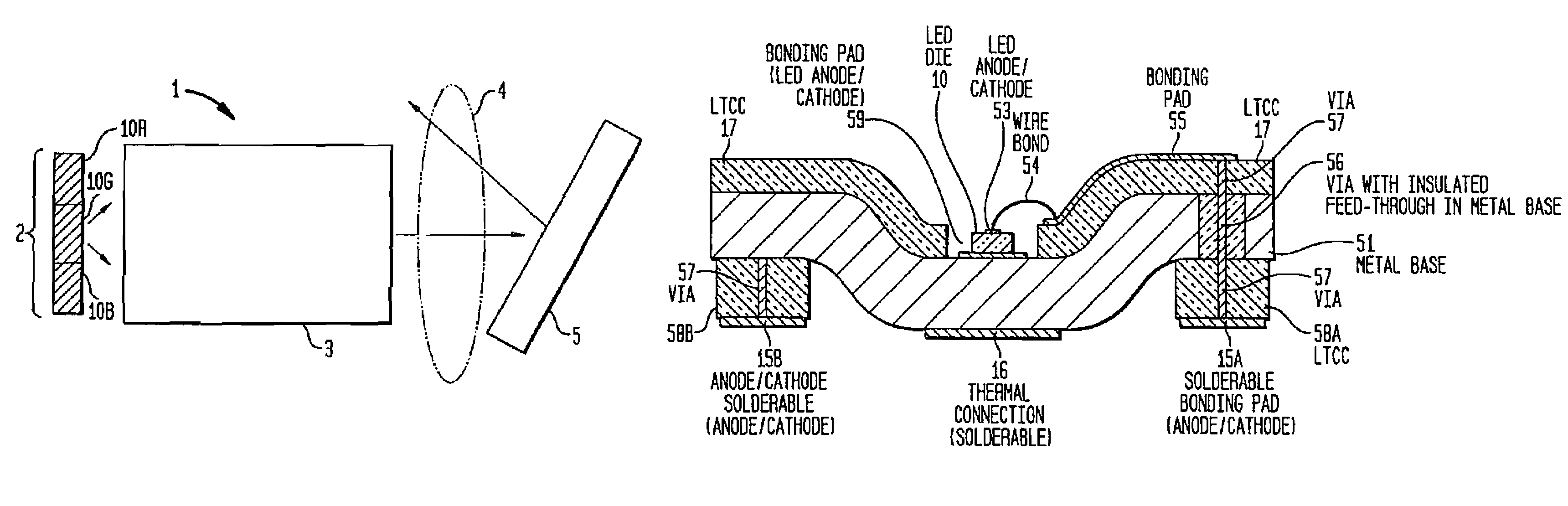
[0063]A part was built using a 13% copper, 74% molybdenum, 13% copper (CMC) metal laminate produced by H. C. Starck Corp. Thick film gold bonding pads are fired on the metal base to correspond to the location of each diode electrode. The pads are connected electrically and thermally to the CMC base. 4 layers of CMC-compatible ceramic tape are used to form the LED cavities, make the electrical connections, and form the array housing. The ceramic tape is composed of glasses and resins supplied by Ferro Corp. and others. The tape materials are ground, mixed, and cast into flat sheets. The sheets are then processed using common “green” tape processing including punching, printing, collating, and laminating.

[0064]The cavities are formed by routing (cutting away material with a rotary tool), pressing the shape using a rigid tool during lamination in the green state, or by punching the cavity in each ceramic layer (green-state punching) using a round punch tool 190 with punch shaft 191 and...


PUM

PropertyMeasurementUnit
thicknessaaaaaaaaaa
surface temperaturesaaaaaaaaaa
temperatureaaaaaaaaaa

Abstract

In accordance with the invention a light source for an image projection system comprises one or more LEDs packaged for high temperature operation. Advantageously, the LED die are disposed on a package comprising a ceramic coated metal base including one or more underlying thermal connection pads, and underlying electrical connection pads, each LED die thermally coupled through the metal base to a thermal connection pad and electrically coupled to electrical connection pads. The LED can be mounted directly on the metal of the base or on a thin coating of electrical insulator on the metal. Arrays of LED die thus packaged are advantageously fabricated by the low temperature co-fired ceramic-on-metal technique (LTTC-M) and can be referred to as LTTC-M packaged arrays. The LEDs are advantageously mounted in an array of cavities having tapered sides to reflect light from the LEDs. The high temperature LED light sources can substitute for HID lamps in a variety of front and rear projection systems and displays. They are particularly useful for rear projection systems.

Description

CROSS REFERENCE TO RELATED APPLICATIONS[0001]This application is a continuation-in-part of U.S. application Ser. No. 10 / 638,579 “Light Emitting Diodes Packaged For High Temperature Operation” filed by Joseph Mazzochette et al. on Aug. 11, 2003 now U.S. Pat. No. 7,095,053 which, in turn, claims the benefit of U.S. Provisional Application Ser. No. 60 / 467,857, of the same title, filed May 5, 2003. The '579 and '857 applications are incorporated herein by reference.FIELD OF THE INVENTION[0002]This invention relates to image projection systems and, in particular, to LED light sources for image projection systems and to systems employing such sources.BACKGROUND OF THE INVENTION[0003]Image projection systems are important communication tools. They permit the conversion of digital or analog information into visual images that can be viewed by audiences as small as one and as large as several thousand.[0004]While there are a wide variety of image projection systems varying from simple slide ...

Claims


Application Information

Patent Timeline
Patent Type & Authority Patents(United States)
IPC IPC(8): G03B21/16H01L27/15H01L25/075H01L33/48H01L33/64
CPCG03B21/00H01L33/486H01L33/642H01L33/647H01L25/0753H01L2224/48227H01L2224/48091H01L2924/00014G03B21/005F21V33/00G03B21/16H01L25/0655G03B21/14
Inventor MAZZOCHETTE, JOSEPH
Owner LIGHTING SCI GROUP
Why Eureka
Try Eureka