
Covering device

a technology of a cover and a sleeve, which is applied in the direction of portable power driven saws, grinding machines, sawing apparatuses, etc., can solve the problem that the additional biasing force cannot be compensated, and achieve the effect of forming a formlocking connection particularly easy and easily separated from each other

Active Publication Date: 2007-11-27
HILTI AG
View PDF4 Cites 21 Cited by
  • Summary
  • Abstract
  • Description
  • Claims
  • Application Information

AI Technical Summary

Benefits of technology

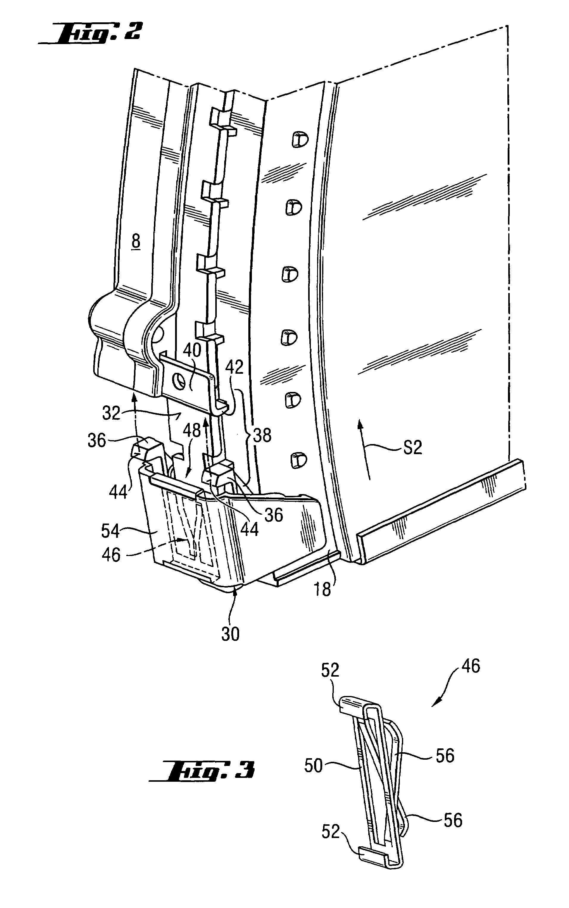
The present invention provides a locking device for a power tool that can securely adjust the position of a guide member relative to a cover in different directions. This allows for easy and comfortable retention of the desired operational depth, while also ensuring optimal suction conditions. The locking device automatically secures the guide member when it reaches a position relative to the cover that corresponds to the set operational depth, eliminating the need for separate adjustment. The connection means and counter-connection means form an operational formlocking connection when the guide member reaches the desired working depth, allowing for easy and separate adjustment of the locking device. The locking spring is formed as one-piece with the depth stop, allowing for easy disconnection and re-setting of the working depth. Overall, the locking device provides improved and convenient adjustability and retention of the guide member position.

Problems solved by technology

This is because the additional biasing force needs not to be compensated.

Method used


Image

  • Covering device
  • Covering device
  • Covering device

Examples


Embodiment Construction

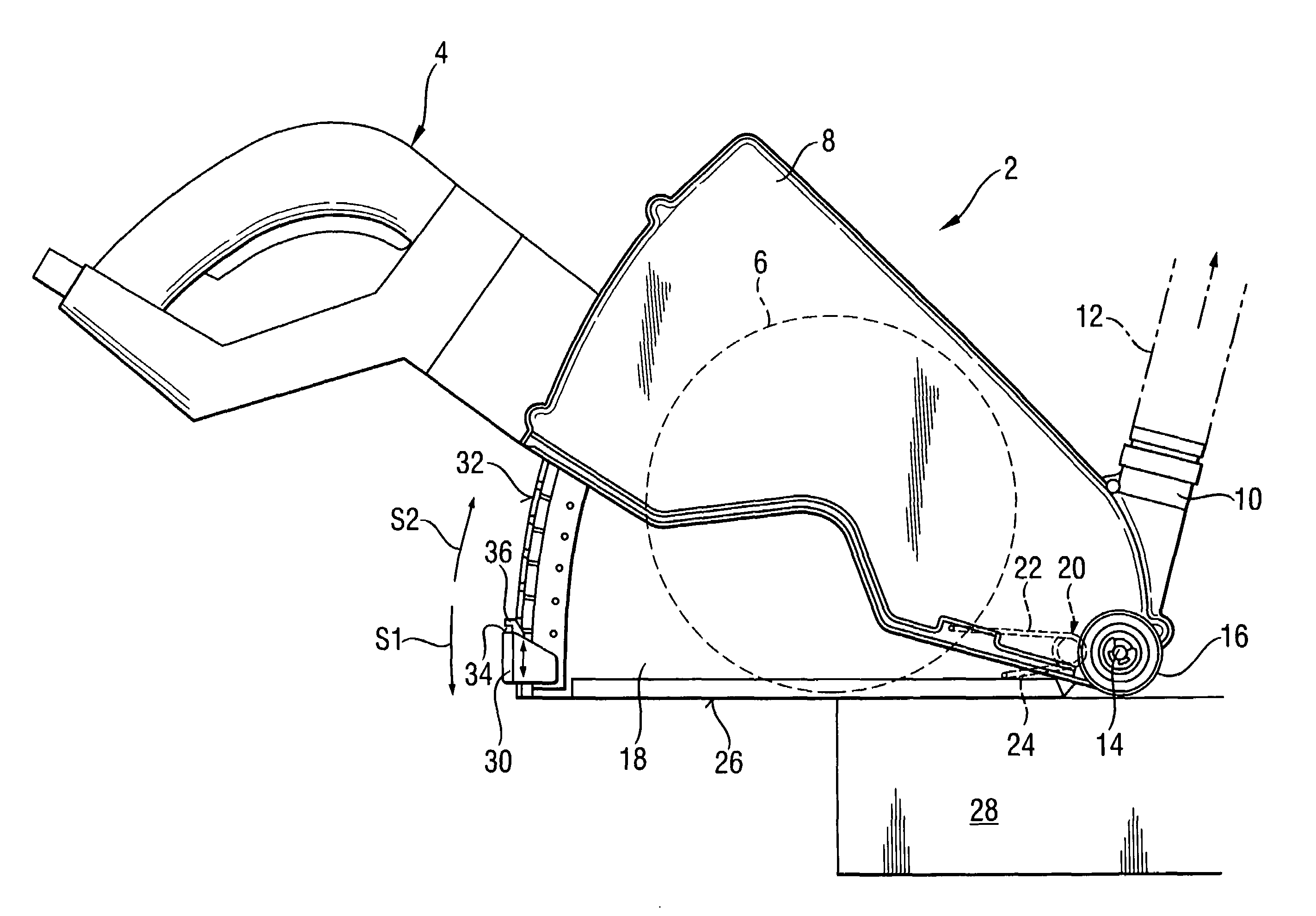
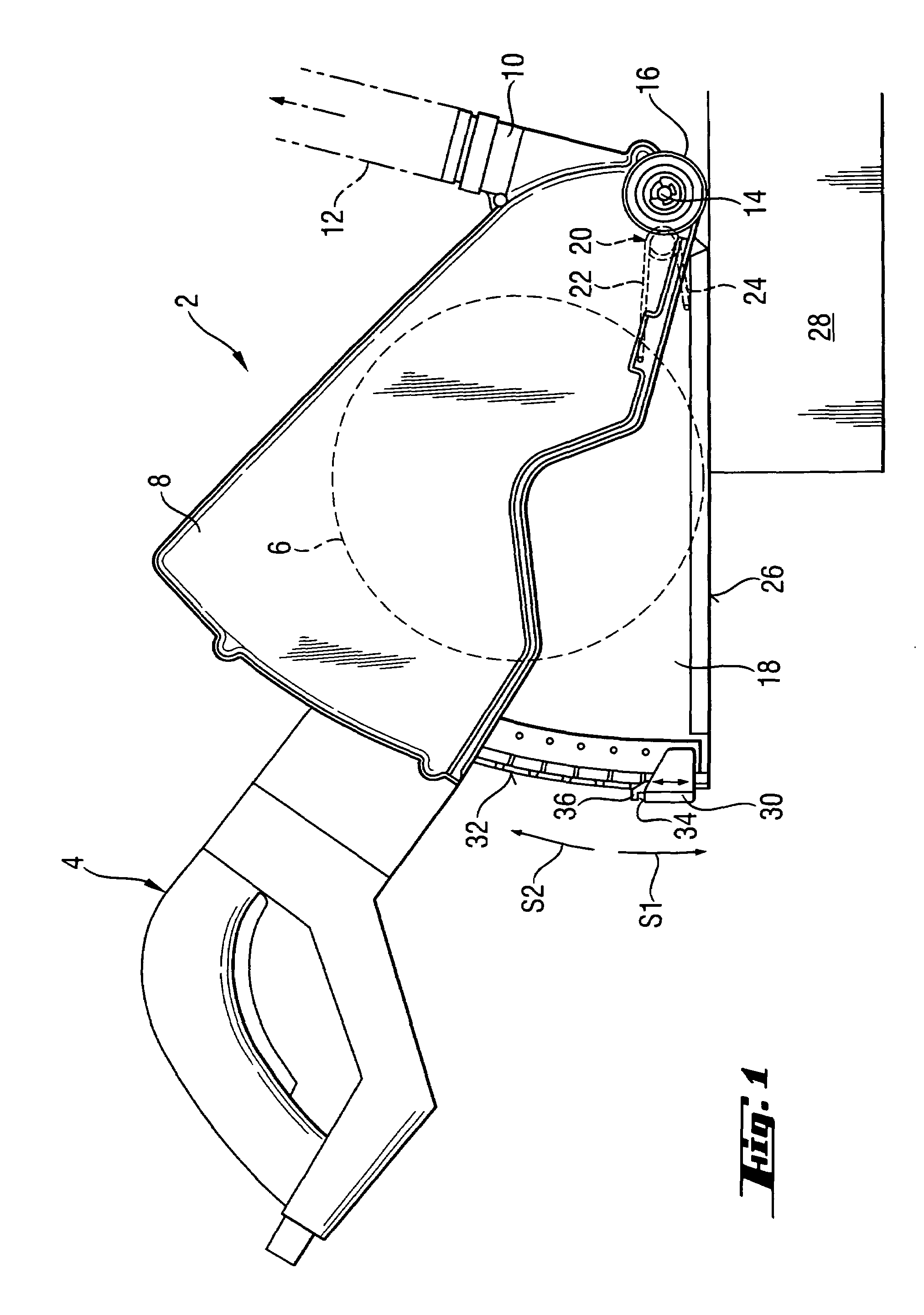
[0024]FIG. 1 shows a covering device 2 of a hand-held electrical power tool 4 in form of a combined cutting, slitting and grinding power tool for treating mineral workpieces and which drive a substantially circular working tool 6 in form of cutting or grinding disc or a slitting tool.

[0025]The covering device 2 includes a cover 8 which is secured on the power tool 4 and encloses the working tool 6. On the cover 8, there is provided a connection union 10 for connecting the cover 8 with dust suction means 12 that are not shown in detail. A guide member 18 is pivotally supported on the cover 8 by a pivot support that is formed by an axle 14 of a roller 16. The guide member 18 is preloaded in a first pivot direction S1 away from the cover 8 by a torsion spring 20. The torsion spring 20 engages with its first leg 22 the cover 8 and with its second leg 24 the guide member 18.

[0026]The guide member 18 has a bearing surface 26 that abuts, during operation of the power tool 4, a treated work...


PUM


Abstract

A covering device (2) for a power tool (4) for driving a circular working tool (6) includes a cover (8) for enclosing the circular working tool (6), a guide member (18) pivotally supported on the cover (8) for being placed onto the workpiece (28), a spring for biasing the guide member (18) in a first pivot direction (S1) away from the cover (8) and an adjustable depth stop (30) a locking device (38) for additionally adjustably securing the guide member (8) in a direction of the first pivot direction (S1).

Description

BACKGROUND OF THE INVENTION[0001]1. Field of the Invention[0002]The present invention relates to a covering device for a power tool for driving a circular working tool such as, e.g., a power saw, furrow tool, or grinding tool and including a cover for enclosing the circular working tool. The covering device further includes a guide member pivotally supported on the cover for being placed onto the workpiece. The guide member is biased in a first pivot direction away from the cover by a spring. The covering device further includes an adjustable depth stop which provides for displacement of the guide member in a second pivot direction opposite the first pivot direction for placing the guide member onto the cover.[0003]2. Description of the Prior Art[0004]Covers of the type described above provide a particular good protection of the rotatable working tool during operation because the guide member is continuously pressed against the workpiece. Thereby, an almost complete covering of the ...

Claims


Application Information

Patent Timeline
Patent Type & Authority Patents(United States)
IPC IPC(8): B24B55/04
CPCB24B55/052B27G19/04B27B9/02
Inventor GAUL, HANS-DIETEROSTERMEIER, PETER
Owner HILTI AG
Learn More