

Process for conversion of organic, waste, or low-value materials into useful products
a technology of low-value materials and processing methods, applied in the field of processing waste or low-value products, can solve the problems of large volume of waste products containing largely organic materials produced by the industry, significant economic and environmental pressures, and the processing industry continues to grow, so as to suppress the hydrolysis of carbohydrates, and encourage the dissociation of amines
- Summary
- Abstract
- Description
- Claims
- Application Information
AI Technical Summary
Benefits of technology
Problems solved by technology
Method used
Image

Examples
example 1
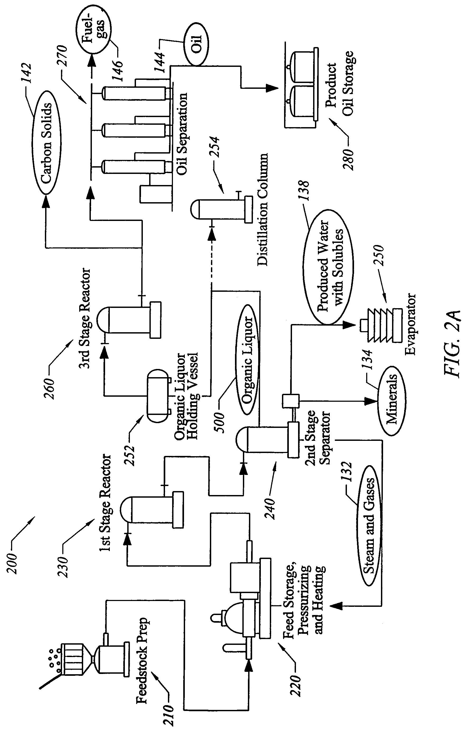
Pilot Plant
[0143]A pilot plant has been built employing apparatus and processes of the present invention. The pilot plant can handle approximately seven tons of waste per day.
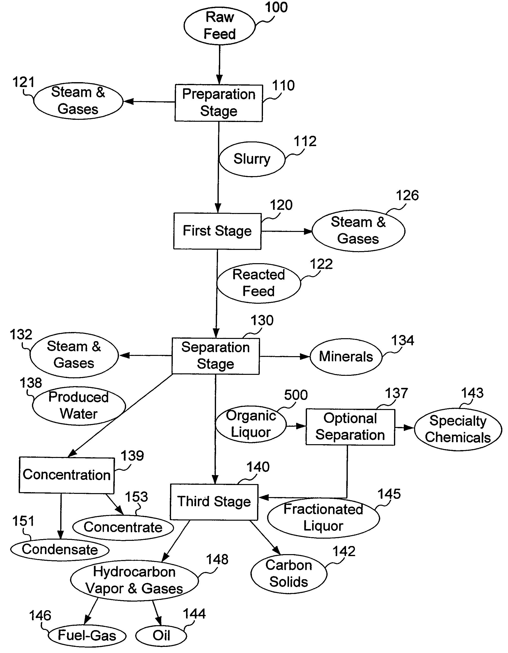
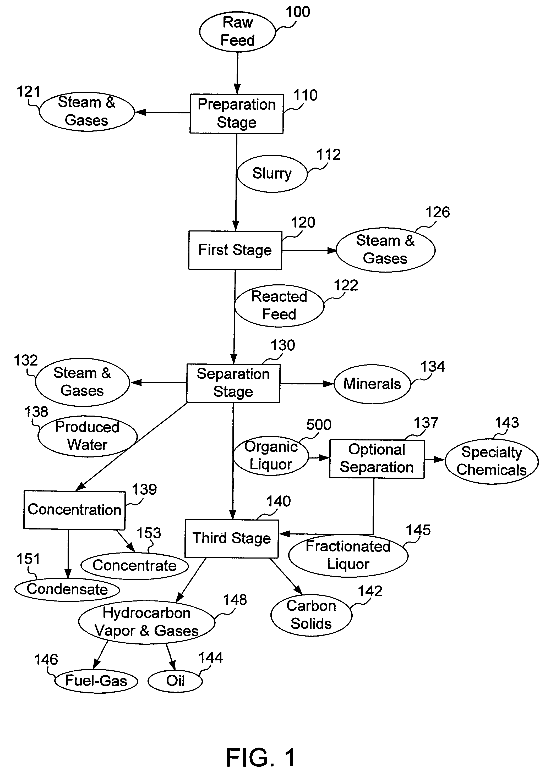
[0144]According to one exemplary application of the pilot plant, the experimental feedstock was turkey processing-plant waste: feathers, bones, skin, blood, fat, viscera. An amount of 10,044 pounds of this material was put into the apparatus's first stage: a 350-horsepower grinder, which turns the material into gray-brown slurry. From there, the material flowed into a series of tanks and pipes which heated and reformed the mixture.
[0145]Two hours later, a light-brown stream of steaming fine oil was produced. The oil produced by this process is very light. The longest carbon chains are C20. The produced oil is similar to a mix of half fuel oil, half gasoline.
[0146]The process of the present invention has proved to be 85% energy efficient for complex feedstocks such as turkey offal. This means that for every 100 ...
example 2
Operating Plant
[0152]A full-sized commercial-scale installation is under construction, intended to process over 200 tons of turkey-waste daily. The plant is designed to produce about 10 tons of gas per day, which returns to the system to generate heat to power the system. The plant will produce about 21,000 gallons of water, which is clean enough to discharge into a municipal sewage system, and is also free of pathological vectors. The plant also will make about 25 tons of minerals, concentrate and carbon, and about 500 barrels of high-quality oil of the same grade as a #2 heating oil.
example 3
Exemplary Conversions of Waste Products
[0153]Table 1 shows end-products, and their proportions, for 100 lbs of each of the following waste product, when they are converted to useful materials using the process of the present invention: Municipal Sewage Waste (comprising 75% sewage sludge and 25% grease-trap waste); Poultry Processing Waste (comprising organs, bones, blood, feathers and fat); Paper; and Heavy Oil (such as refinery-vacuum residues and tar sands). Amounts in Table 1 are in pounds.
[0154]
TABLE 1FeedstockOilGasSolids & ConcentrateWaterMunicipal269 8 (carbon and mineral solids) †57Sewage SludgePoultry396 5 (carbon and mineral solids)50Processing WastePaper ‡84824 (carbon solids)20Heavy Oil7417 9 (carbon solids).—‡ For paper, the figures are based on pure cellulose; it is estimated that yields for specific paper feedstocks such as newspapers or office waste paper would be within 10 % of these figures.† The solid output from municipal sewage sludge may also contain heavy met...
PUM
| Property | Measurement | Unit |
|---|---|---|
| pressure | aaaaa | aaaaa |
| pressure | aaaaa | aaaaa |
| temperature | aaaaa | aaaaa |
Abstract
Description
Claims
Application Information