
Double-sided flexible printed circuits

a printed circuit and flexible technology, applied in the direction of flat/ribbon cables, insulated conductors, cables, etc., can solve the problem of contact pressure of contacts differing with the position of pads

Inactive Publication Date: 2007-11-27
JST MFG CO LTD
View PDF12 Cites 21 Cited by
  • Summary
  • Abstract
  • Description
  • Claims
  • Application Information

AI Technical Summary

Benefits of technology

The present invention provides a double-sided FPC (flexible printed circuit) that can connect to a connector with multi-pin contacts. The double-sided FPC has a reinforced structure at the areas where the terminals press upon the connector contacts to prevent deformation. The FPC has copper foil laminated on both faces of the insulating base, with pluralities of first and second conductive patterns disposed in parallel and exposed on the terminal. The first and second conductive patterns are pressed upon the first and second contacts on the connector, respectively. The double-sided FPC is designed to have a narrow profile and a low profile, which makes it ideal for use in thin and flexible devices. The connector used with the double-sided FPC is a ZIF (Zero Insertion Force) connector.

Problems solved by technology

The fact that contact pressure of the contacts differs with positions of the pads is a problem from the viewpoint of reliability.

Method used


Image

  • Double-sided flexible printed circuits
  • Double-sided flexible printed circuits
  • Double-sided flexible printed circuits

Examples


Embodiment Construction

[0054]A best mode for implementing the present invention is explained below, referring to the drawings.

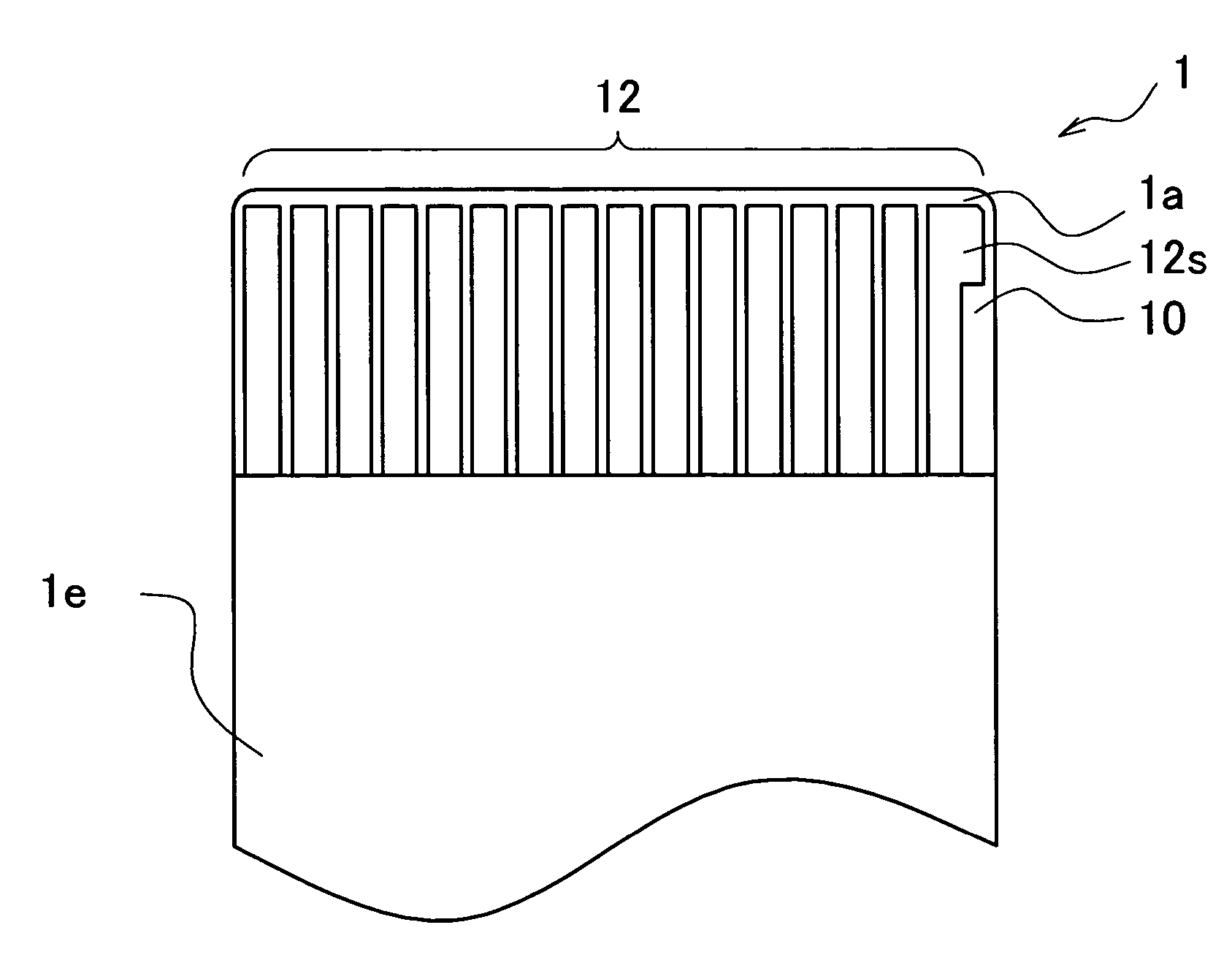
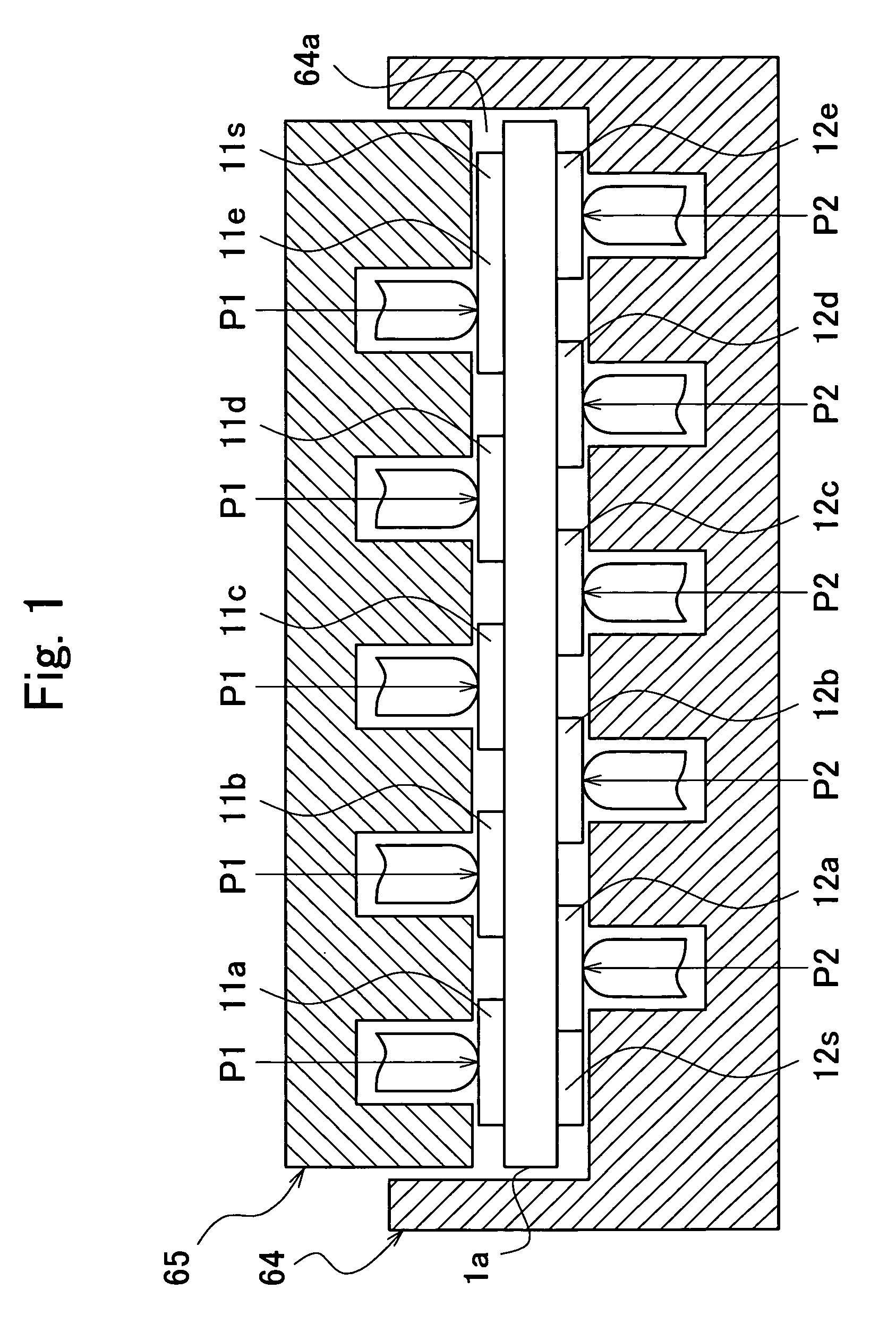
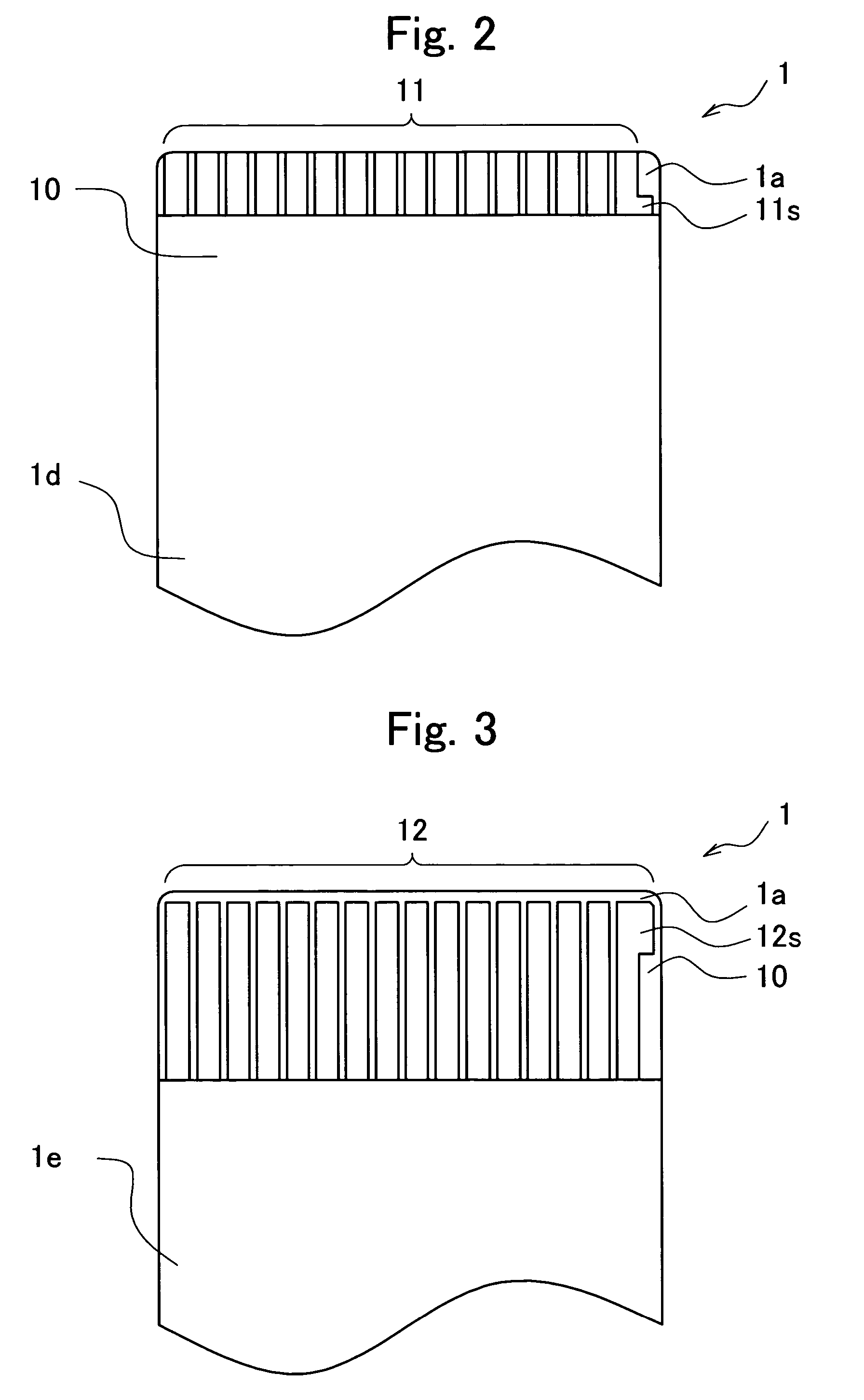
[0055]FIG. 1 is a top view of an embodiment of the double-sided FPC according to the present invention. FIG. 2 is a plan view of Embodiment 1 of the double-sided FPC according to the present invention and of one face (front face) of the FPC. FIG. 3 is a plan view of the double-sided FPC according to Embodiment 1, and is a view of the other face (rear face) of the FPC. FIG. 4 is plan view of Embodiment 2 of the double-sided FPC according to the present invention. FIG. 4 is a view of one face (front face) of the FPC. FIG. 5 is a plan view of the double-sided FPC according to Embodiment 2, and is a view of the other face (rear face) of the FPC. FIGS. 6A and 6B are enlarged views of main parts of the double-sided FPC according to Embodiment 2. FIG. 6A is an enlarged view of a first conductive pattern at an end, and FIG. 6B is an enlarged view of a second conductive pattern at an end. F...


PUM


Abstract

A double-sided flexible printed circuit comprises: an electrically insulating base; a first copper layer having a first conductive pattern; a second copper layer having a second conductive pattern, the second conductive pattern disposed offset from the first conductive pattern; and electrically insulating coverlays. A first area opposing a first contact point of first contacts that press upon the first conductive patterns, is reinforced by copper foil extending from the second conductive patterns, and a second area opposing a second contact point of second contacts that press upon the second conductive patterns, is reinforced by copper foil extending from the first conductive patterns.

Description

[0001]This application is based on and claims the benefit of priority from Japanese Patent Application No. 2005-009607, filed on Jan. 17, 2005, the content of which is incorporated herein by reference.BACKGROUND OF THE INVENTION[0002]1. Field of the Invention[0003]The present invention relates to flexible flat cables (printed circuits that are flexible) such as FPCs (Flexible Printed Circuits), FFCs (Flexible Flat Cables), and the like. In this specification, a flexible flat cable is generically referred to as an FPC. The present invention relates, in particular, to a connecting structure for a terminal of a double-sided FPC connected to an FPC connector.[0004]2. Related Art[0005]In electronic devices in recent years, flexible flat cables (FPCs) are used for connecting printed circuit boards and electronic component modules mounted in portable information devices typified by, for example, DVCs (Digital Video Cameras), DSCs (Digital Still Cameras), cell-phones, and PDAs (Personal Dig...

Claims


Application Information

Patent Timeline
Patent Type & Authority Patents(United States)
IPC IPC(8): H05K1/00
CPCH05K1/118H05K1/117H05K3/281H05K3/325H05K2203/1572H05K2201/094H05K2201/09709H05K2201/09781H05K2201/09145
Inventor MIURA, KAZUTOYAMANE, HIROSHINAKAI, YOSHIYUKITODA, KENICHI
Owner JST MFG CO LTD
Learn More