Small broadband helical antenna

a broadband antenna and helical antenna technology, applied in the field of small broadband helical antennas, can solve the problems of insufficient electrical characteristics of a “rubber ducky” antenna, obstructive, costly, and bulky “rubber ducky” antennas, and achieve the effect of reducing the cost of wireless devices

Active Publication Date: 2007-11-27
SHURE ACQUISITION HLDG INC
View PDF5 Cites 27 Cited by
  • Summary
  • Abstract
  • Description
  • Claims
  • Application Information

AI Technical Summary

Benefits of technology

[0008]With another aspect of the invention, the pitch of the conductive portion of the tape assembly is determined to provide desired electrical characteristics when the tape assembly is wrapped around the dielectric core.

Problems solved by technology

Radio antennas are typically bulky and incur a cost that may adversely increase the price of a wireless device.
Consequently, a “rubber ducky” antenna is often bulky, obstructive, and costly.
Moreover, the electrical characteristics of a “rubber ducky” antenna may be insufficient.
Additionally signal loss due to the proximity of a user's hand may be excessive.

Method used


Image

  • Small broadband helical antenna
  • Small broadband helical antenna
  • Small broadband helical antenna

Examples


Embodiment Construction

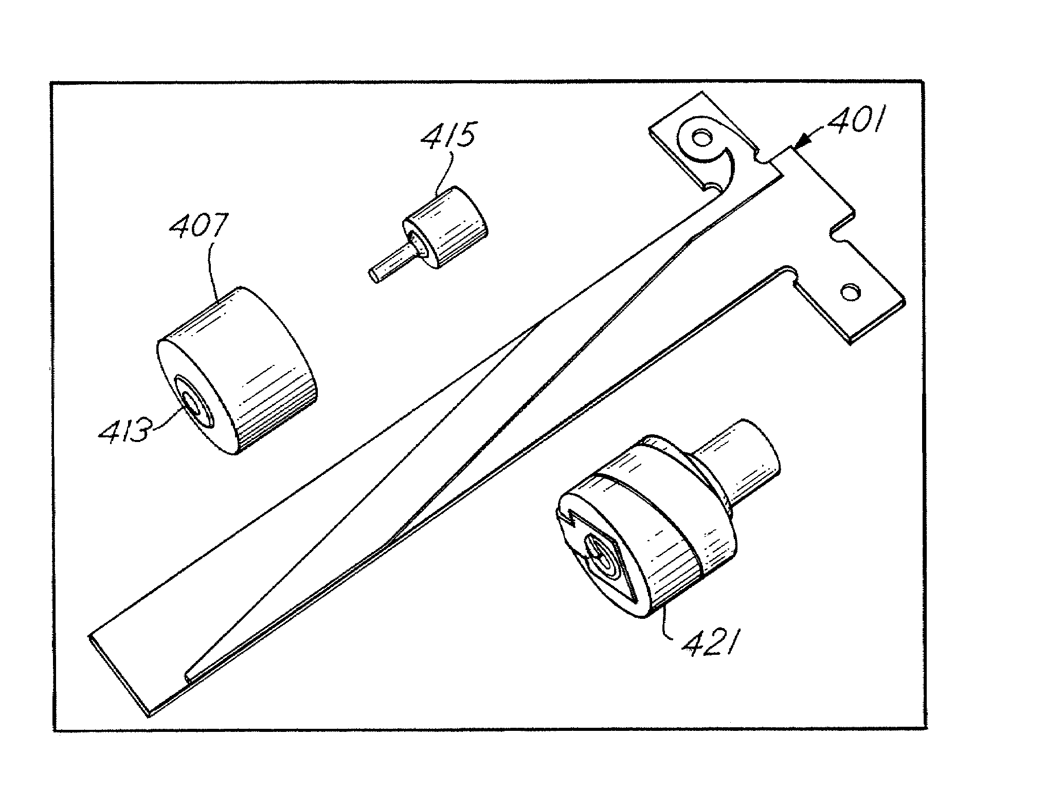
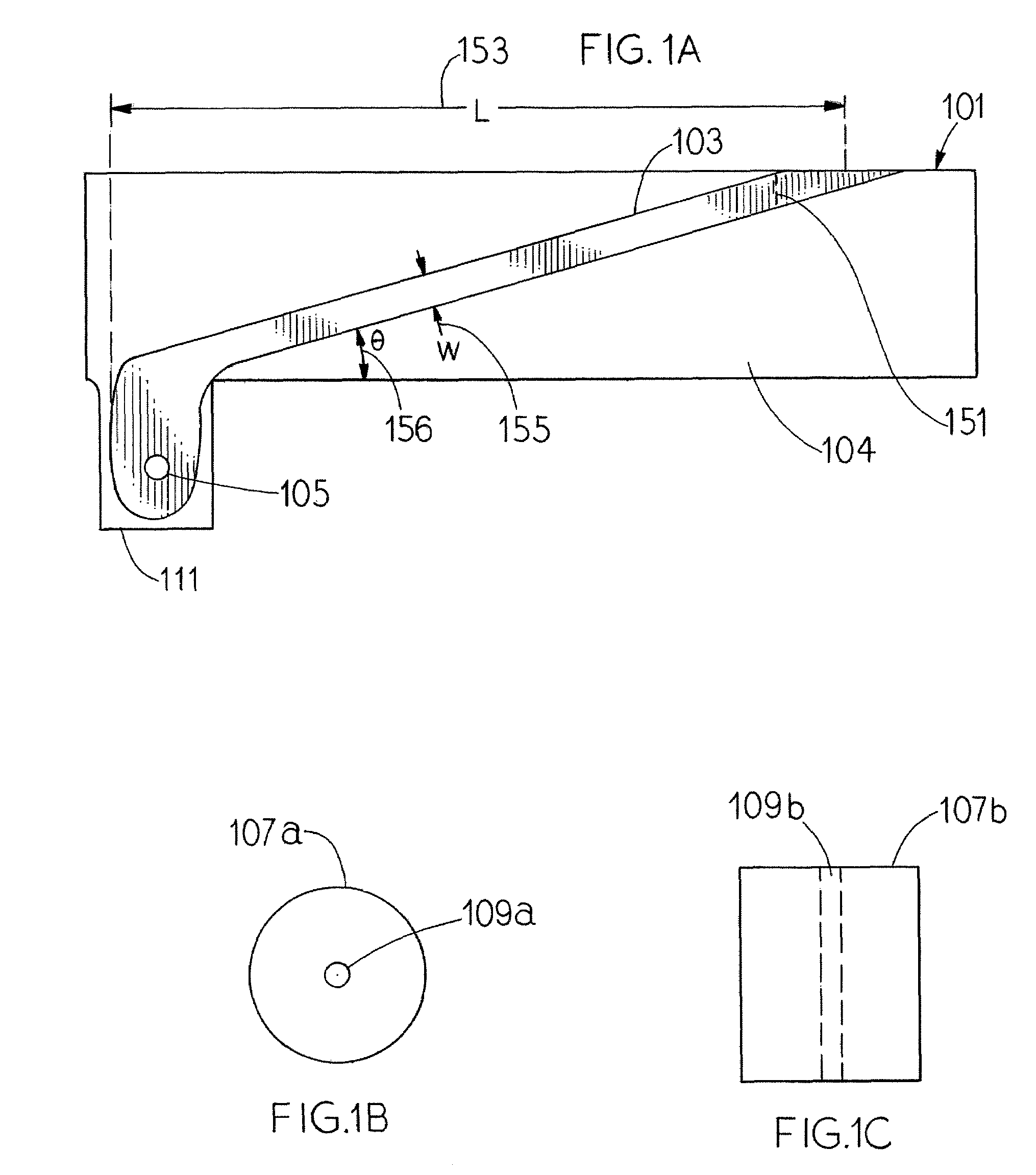
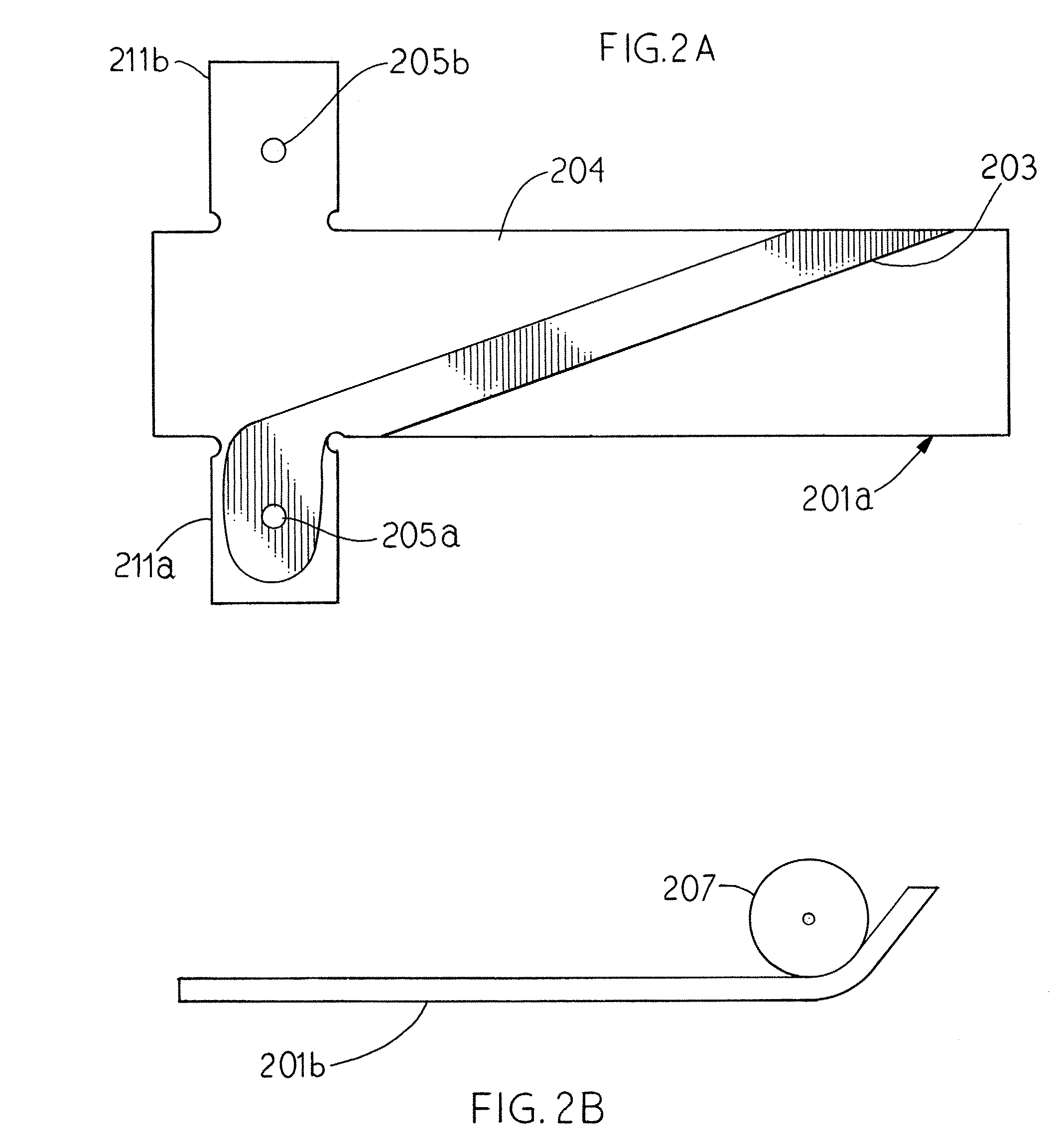
[0020]FIG. 1 shows components of a broadband helical antenna in accordance with an embodiment of the invention. Tape assembly 101 comprises base portion 104 and conductive portion 103 (which comprises copper tape in the embodiment shown). In the embodiment, base portion 104 is constructed from a vinyl core material that is laminated with copper tape 103 with electro tin plating. (In the embodiment shown, 3M™ number 9471 adhesive with an approximate thickness of 2.0 mils is used for laminating the copper tape 103 with base portion 104. Copper tape 103 may be electroplated on base portion 104 and laser trimmed or mechanically trimmed to provide the desired width and length dimensions. Also, as will be discussed, copper tape 103 may be subsequently cut at line 151, in which the excessive length of copper tape is removed, in order to adjust and tune the helical antenna assembly. The frequency characteristics are determined by a number of parameters that include length (L) 153, width (W)...


PUM


Abstract

The invention provides methods and apparatuses for a helical antenna assembly that are constructed by placing a metallic tape strip diagonally onto non-metallic tape. The tape assembly is then rolled on a dielectric core. The metallic tape strip is coupled to an electrical connector and a center conductor that is located through the center of the dielectric core. The tape assembly may include one or two tabs that are bent over the ends the dielectric core to prevent the tape assembly from separating from the dielectric core. The tabs may be pinned by eyelets that are affixed to the center conductor. The pitch of the conductive portion of the tape assembly is determined to provide desired electrical characteristics when the tape assembly is wrapped around the dielectric core. The conductive portion of the tape assembly may be trimmed to obtain desired electrical characteristics.

Description

[0001]This application claims priority to provisional U.S. Application Ser. No. 60 / 650,249 (“Small Broadband Helical Antenna”), filed Feb. 4, 2005.FIELD OF THE INVENTION[0002]The invention relates to small broadband antennas, and more particularly helical antennas that may be used with wireless microphones.BACKGROUND OF THE INVENTION[0003]Wireless applications are becoming even more prevalent with the growing utilization of untethered computers, wireless telephones, and other wireless devices. However, in order to effectively support wireless applications, a RF signal is typically transmitted or received between wireless devices through a radio antenna. Radio antennas are typically bulky and incur a cost that may adversely increase the price of a wireless device. A “rubber ducky” antenna is an example of a radio antenna that is popularly used in wireless applications. A “rubber ducky” antenna is often constructed by wrapping wire around a core insulator and covered by protective mat...

Claims


Application Information

Patent Timeline
Patent Type & Authority Patents(United States)
IPC IPC(8): H01Q1/36
CPCH01Q1/22H01Q11/08H01Q1/362H01Q1/36H01Q9/27
Inventor KENKEL, MARK ALLENBAUMAN, STUART P.
Owner SHURE ACQUISITION HLDG INC
Why Eureka
Try Eureka