Optimization of near field antenna characteristics by aperture modulation

a near field antenna and aperture modulation technology, applied in the field of antennas, can solve the problems of serious degradation of far field performance, unsatisfactory application characteristics, and non-uniform distribution, and achieve the effect of simple and inexpensiv

Inactive Publication Date: 2007-11-27
THE UNITED STATES OF AMERICA AS REPRESETNED BY THE SEC OF THE AIR FORCE
View PDF4 Cites 149 Cited by
  • Summary
  • Abstract
  • Description
  • Claims
  • Application Information

AI Technical Summary

Benefits of technology

[0012]An embodiment of the present invention provides a simple and inexpensive means for controlling the near field (Fresnel zone) characteristics of microwave transmitting antennas. The antenna aperture is divided into two sections with the inner section connected to the outer section by a small number of transducers that can be individually driven by a programmable driver. The transducers are used to vary the relative position of the inner section of the antenna aperture with respect to the outer section of the antenna aperture, approximating a concave or convex shape. Controlling the effective radius of curvature of the spherical phase front (focal length) at the antenna aperture controls the spot characteristics within the near field of the antenna. Furthermore, this embodiment can also vary the tilt angle of the inner section to control the off axis position of the radiated beam or to trace out a scan pattern.

Problems solved by technology

When the focal length is negative, as in FIG. 3, the far field performance is seriously degraded.
In addition, for all ranges the total power of the beam is confined to about the same outer diameter although the distribution is non-uniform.
These characteristics are not ideal for applications that require a concentration of the beam power that is confined to an area and does not vary greatly in magnitude over the concentration area.
This is very difficult to implement in that it would require an aperture phased array of hundreds of thousands of elements or a precisely mechanically deformable aperture.
Neither of these options is feasible as a practical matter.

Method used


Image

  • Optimization of near field antenna characteristics by aperture modulation
  • Optimization of near field antenna characteristics by aperture modulation
  • Optimization of near field antenna characteristics by aperture modulation

Examples


Embodiment Construction

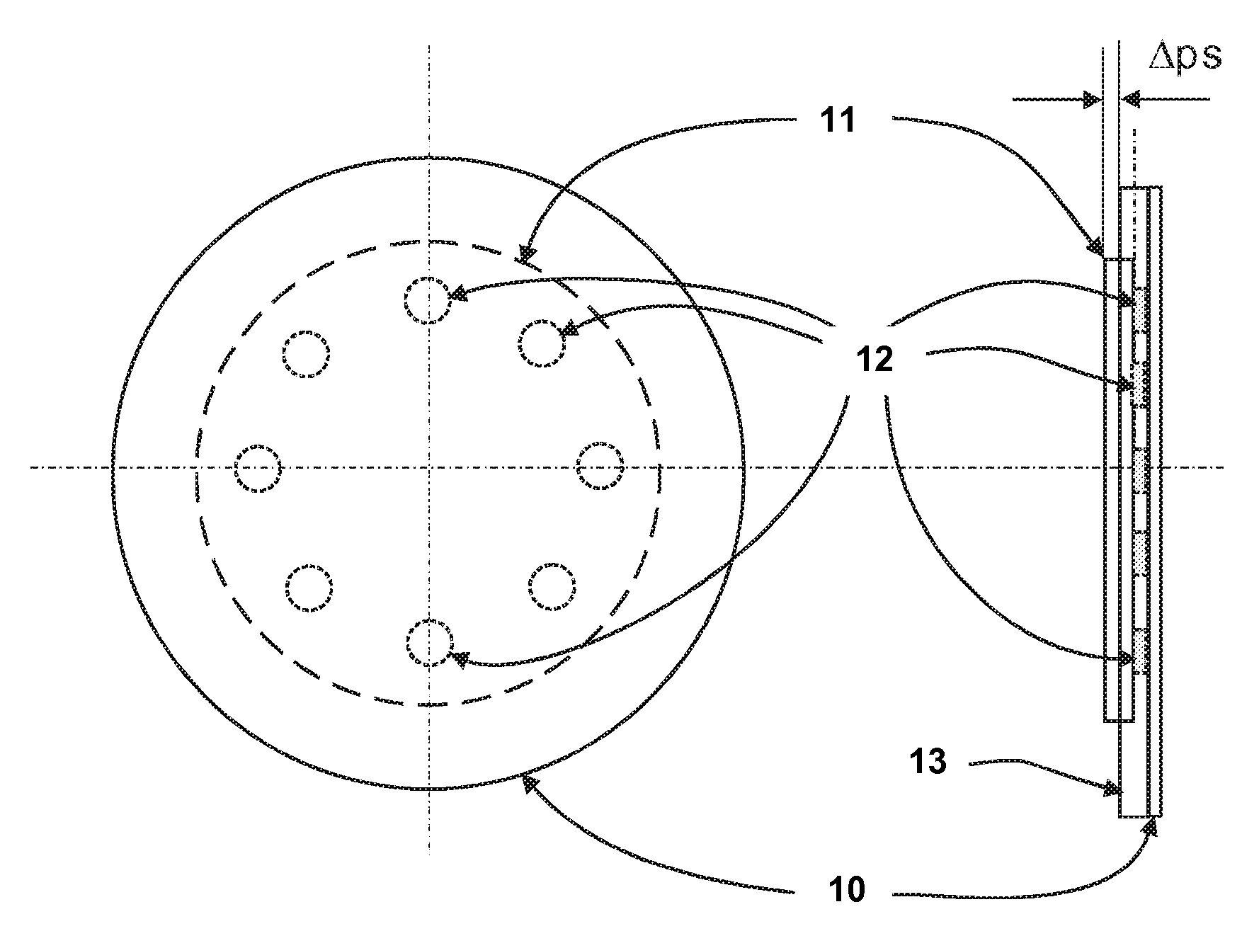
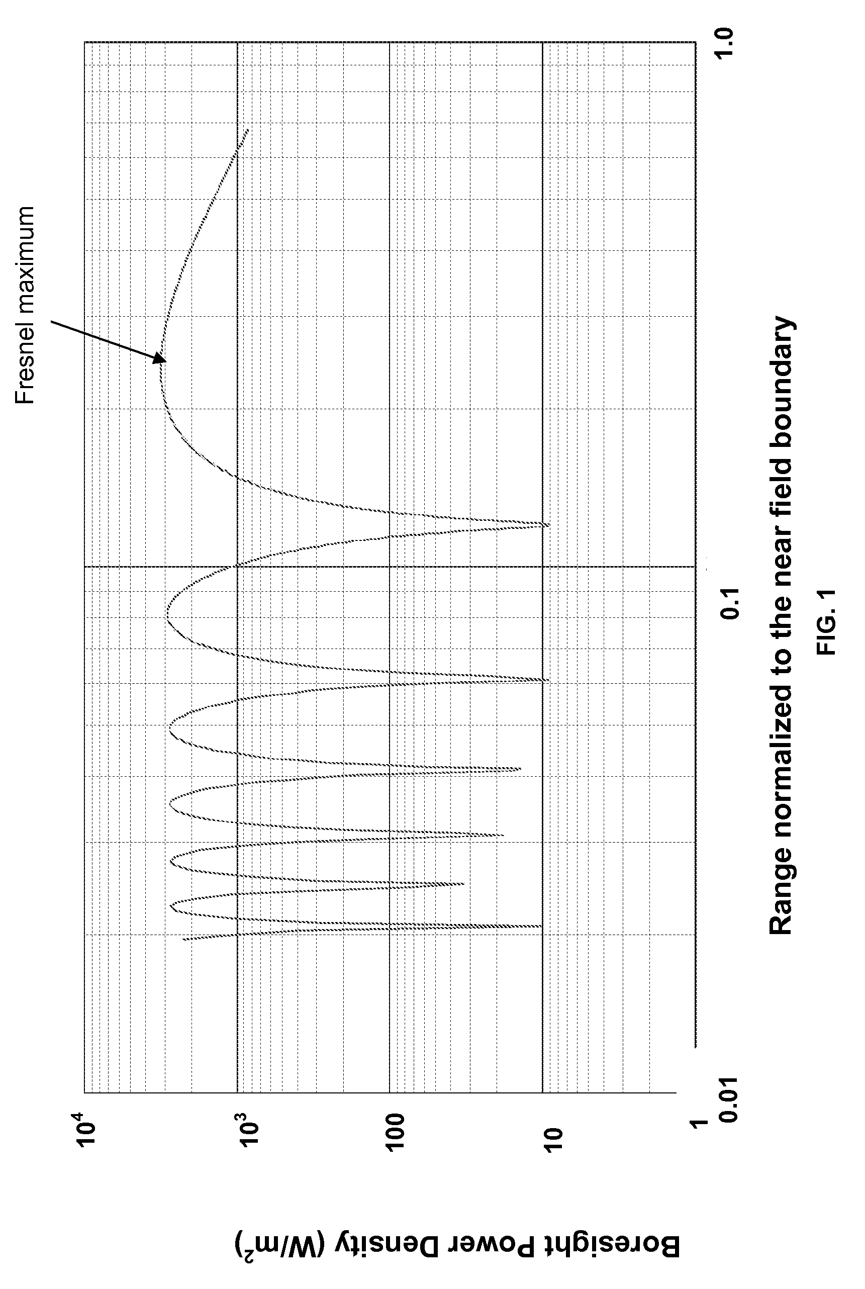
[0027]The near field of an aperture antenna is comprised of a non-radiating reactive region in the space immediately surrounding the antenna and the radiating near field region referred to as the Fresnel region, the region of primary interest in the following discussion. This region extends from the outer boundary of the reactive region given approximately by:

RrrD3 / λ)

where D is the largest dimension of the antenna and λ is the transmitting wavelength. The outer boundary of the Fresnel region is approximately given by:

Rnf≈D2 / λ

which for the earlier example would give an approximate range of 11 to 333 meters.

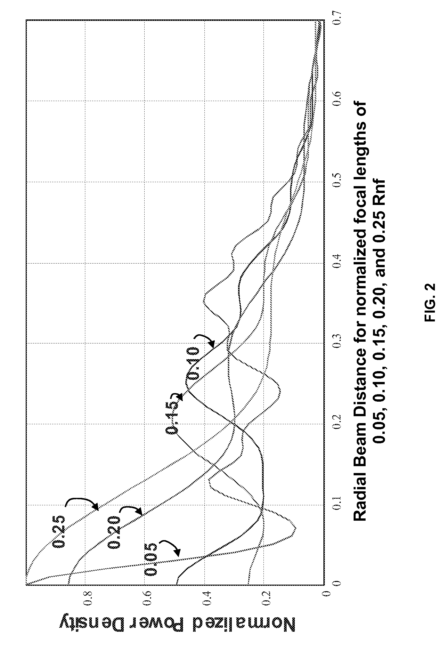
[0028]It has been shown above that conventional aperture antennas have non-uniform power density distributions in the near field region and are, therefore, poor in performance for applications that require a concentrated beam that is reasonably uniform over the beam area. It has also been shown that if one can control the focal length or the radius of curvature of the phase front o...


PUM


Abstract

The approximate radius of curvature of the spherical phase front at the aperture of a transmitting microwave antenna is controlled by an inner section of the aperture attached to the outer section of the aperture by a small number of programmable transducers, thereby controlling the near field shape and power distribution of the transmitted beam.

Description

STATEMENT OF GOVERNMENT INTEREST[0001]The conditions under which this invention was made are such as to entitle the Government of the United States under paragraph I(a) of Executive Order 10096, as represented by the Secretary of the Air Force, to the entire right, title and interest therein, including foreign rights.BACKGROUND OF THE INVENTION[0002]This invention relates generally to the field of antennas and more specifically provides a means of control and optimization of the near field behavior of a microwave transmitting antenna.[0003]Microwave transmitting antennas of the aperture type or equivalent operating at millimeter wavelengths have an equivalent aperture diameter that is many wavelengths that defines a near field region extending as far as hundreds of meters. The near field range (Rnf) of an antenna is defined as a range that is less than Rnf≈D2 / λ. This is referred to as the near field boundary. D is the equivalent diameter of the antenna and A is the wavelength, all q...

Claims


Application Information

Patent Timeline
Patent Type & Authority Patents(United States)
IPC IPC(8): H01Q15/20H01Q19/12
CPCH01Q3/46H01Q19/12H01Q19/10
Inventor O'LOUGHLIN, JAMES P.
Owner THE UNITED STATES OF AMERICA AS REPRESETNED BY THE SEC OF THE AIR FORCE
Why Eureka
Try Eureka