Low profile speaker and system

a speaker and low-profile technology, applied in the field of compact speakers and speaker/enclosure systems, can solve the problems of increasing the cost of small speakers, increasing the cost of enclosures, and increasing the cost of speakers, so as to enhance the response, reduce the depth, and enhance the spatial fidelity of sound reproduction

Inactive Publication Date: 2007-11-27
NUTTER MCCLENNEN & FISH
View PDF59 Cites 17 Cited by
  • Summary
  • Abstract
  • Description
  • Claims
  • Application Information

AI Technical Summary

Benefits of technology

[0010]One or more of these and other desirable features are attained in a speaker in accordance with the present invention wherein the speaker has a magnet structure defining a flux gap, a voice coil residing in the flux gap, and a main diaphragm connected to the voice coil such that drive current applied to the voice coil moves the diaphragm to generate sound. The main diaphragm is connected to the voice coil at a back plane and extends forward of the back plane, while the voice coil and magnet structure are centered on the main diaphragm in a location ahead of the back plane, thus forming a speaker of reduced depth. Thus, the flux gap is at the rear of the magnet structure, which is ahead of the main diaphragm. In a preferred embodiment, the magnet structure has an additional flux gap located at its forward end, and the speaker includes an additional diaphragm driven by a coil positioned in the additional flux gap. The main diaphragm and additional diaphragm may be positioned to maintain a common sound center for enhanced spatial fidelity of sound reproduction, and provide pinpoint definition free of the apparent spatial wandering that plagues wide band audio reproduction. The two diaphragms may be actuated independently, or with different bands or frequency portions of the audio signal
[0011]In a preferred embodiment, the magnet structure possesses an opening extending trough the center of the structure, and when mounted in an enclosure this opening communicates with the interior of the enclosure, allowing the front diaphragm to couple with the enclosure and enhance its response. Alternatively, with no front diaphragm present, the additional opening to the enclosure may be used to affect compliance or damping of a small enclosure and enhance response of the system.

Problems solved by technology

For still others, cost is a major factor.
However, the trend to small speakers poses numerous technical problems, especially at the lower frequency end of the spectrum, since a smaller diaphragm is less effective at radiating lower frequencies and, moreover, typically has a higher natural resonance.
When bass response is extended or enriched by coupling to a cabinet or enclosure, the enclosure itself must often be deep or bulky.
Another problem arises when it is desired to provide room-filling sound with a composite system, such as a stereo or surround sound system having multiple speakers or speaker diaphragms each optimized for a sub-band of the audio spectrum.
In this case, when a plurality of separate instruments such as a chorus, a jazz ensemble, or a quartet are to be heard and individually discerned in the resulting sound, the problem arises that the apparent center or source of the sound may wander or jump from place to place as the pitch changes, even when the pitches had originally been produced by and recorded from the same, stationary, instrument.
This problem arises in part because human auditory perception is quite sensitive to phase information, which may change as the sound emanates from different regions—speaker diaphragms or enclosure ports—of the system.
However, the portion of sound emanating from the enclosure also contributes to this effect, making the achievement of true pinpoint sound problematic.
Moreover, physical dimensions of the various magnet, frame and diaphragm structures making up a speaker or speaker system place limits on the proximity of the different sound sources.

Method used


Image

  • Low profile speaker and system
  • Low profile speaker and system
  • Low profile speaker and system

Examples


Embodiment Construction

[0018]The invention may be understood in the context of the constraints imposed in designing small, efficient, high-performance speakers and systems. Reference is hereby made to Applicant's earlier patents and patent applications as follows: U.S. Pat. No. 5,802,191, U.S. application Ser. No. 09 / 100,411, U.S. application Ser. No. 09 / 439,416 and corresponding international application PCT / US99 / 27011, U.S. application Ser. No. 09 / 639,416 and corresponding international application PCT / US00 / 22119. Each of the foregoing patents and applications is incorporated by reference herein in its entirety.

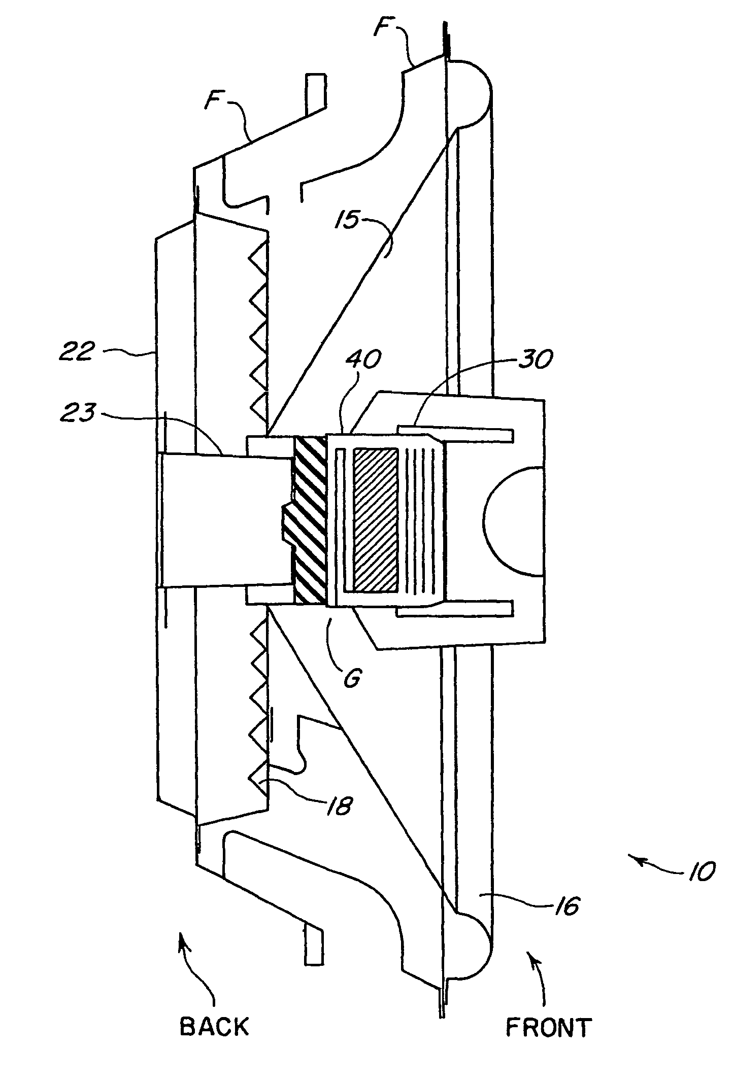
[0019]FIG. 1 illustrates a diametral section through one embodiment of a speaker 10 in accordance with the present invention, showing its structure in detail. The speaker includes a diaphragm 15 (which may interchangeably be referred to herein as a “cone”), supported by a frame F. The cone faces forwardly to project sound, and the frame generally in practice extends into or mounts on an enclosure...


PUM


Abstract

A speaker has a magnet structure mounted ahead of the speaker diaphragm to produce a shallow compact unit. The magnet structure defines a flux gap, and a voice coil residing in the flux gap is connected to a main diaphragm such that drive current applied to the voice coil moves the diaphragm to generate sound. The voice coil and magnet structure provide a flux gap at the rear of the magnet structure, ahead of and centered on the main diaphragm, while the magnet occupies space within the cone, freeing up space in the rear. In one embodiment, the magnet structure has an additional flux gap located at its forward end and the speaker includes an additional diaphragm driven by a coil positioned in the additional flux gap. The main diaphragm and additional diaphragm are better positioned to maintain a common sound center for enhanced spatial fidelity and different tuning techniques present a broad flat response below crossover to form a pinpoint sound source of wide angular coverage. The back wave couples directly into an enclosure, which may be a shallow, panel mount assembly. The magnet structure may possess an opening extending through the center of the structure allowing control over the acoustics through enclosure compliance or damping effects to enhance response of the system.

Description

CROSS-REFERENCE TO RELATED APPLICATION[0001]This application is a continuation of U.S. patent application Ser. No. 10 / 715,230, filed Nov. 17, 2003 now abandoned, entitled “Low Profile Speaker and System,” which is a continuation of U.S. Ser. No. 09 / 895,003, filed Jun. 27, 2001 now abandoned, which claims the benefit of priority of 60 / 214,704, filed Jun. 27, 2000. The teachings of all three of the above-cited applications are incorporated herein by reference.BACKGROUND OF THE INVENTION[0002]The present invention relates to audio speakers and systems, particularly to compact speakers and speaker / enclosure systems.[0003]In recent years, the number of applications to which compact speakers are put has grown substantially. This growth is partly due to the arrival of numerous new forms of consumer electronics and personal electronic music playing devices, many of which require or promote the use of accessory speakers for full volume delivery of high quality sound. The increased use of com...

Claims


Application Information

Patent Timeline
Patent Type & Authority Patents(United States)
IPC IPC(8): H04R25/00H04R9/02H04R9/04H04R9/06
CPCH04R9/02H04R9/06H04R9/025H04R2209/026
Inventor GUENTHER, GODEHARD A.
Owner NUTTER MCCLENNEN & FISH
Why Eureka
Try Eureka