
Surgical stapling instrument incorporating a multi-stroke firing mechanism with a flexible rack

a multi-stroke firing mechanism and flexible rack technology, applied in the direction of surgical staples, surgical forceps, paper/cardboard containers, etc., can solve the problems of affecting the performance of the instrument, the need for a longer handle, and the inability to meet the needs of the patient, so as to reduce the required length of the handle

Inactive Publication Date: 2007-12-04
CILAG GMBH INT
View PDF72 Cites 2663 Cited by
  • Summary
  • Abstract
  • Description
  • Claims
  • Application Information

AI Technical Summary

Benefits of technology

[0011]The invention overcomes the above-noted and other deficiencies of the prior art by providing a surgical stapling and severing instrument that advantageously incorporates a flexible firing member in a handle. The handle guides a distal portion of the flexible firing member longitudinally to translate a firing motion into a shaft firing member that translates in a shaft to actuate a distally attached end effector. The handle deflects a proximal portion of the flexible firing member from the longitudinal axis during retraction to advantageously reduce the required length of the handle.

Problems solved by technology

Moreover, laparoscopic and endoscopic procedures often require the surgeon to act on organs, tissues and / or vessels far removed from the incision.
Thus, instruments used in such procedures are typically long and narrow while being functionally controllable from a proximal end of the instrument.
In addition, some surgeons not familiar with the larger staple cartridges may become concerned that binding or other malfunction has occurred when an unexpectedly higher force is required.

Method used


Image

  • Surgical stapling instrument incorporating a multi-stroke firing mechanism with a flexible rack
  • Surgical stapling instrument incorporating a multi-stroke firing mechanism with a flexible rack
  • Surgical stapling instrument incorporating a multi-stroke firing mechanism with a flexible rack

Examples


Embodiment Construction

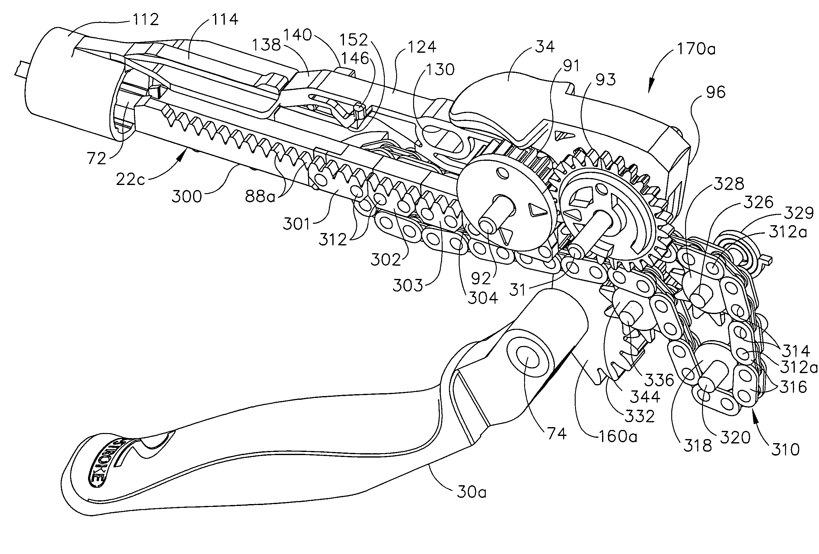
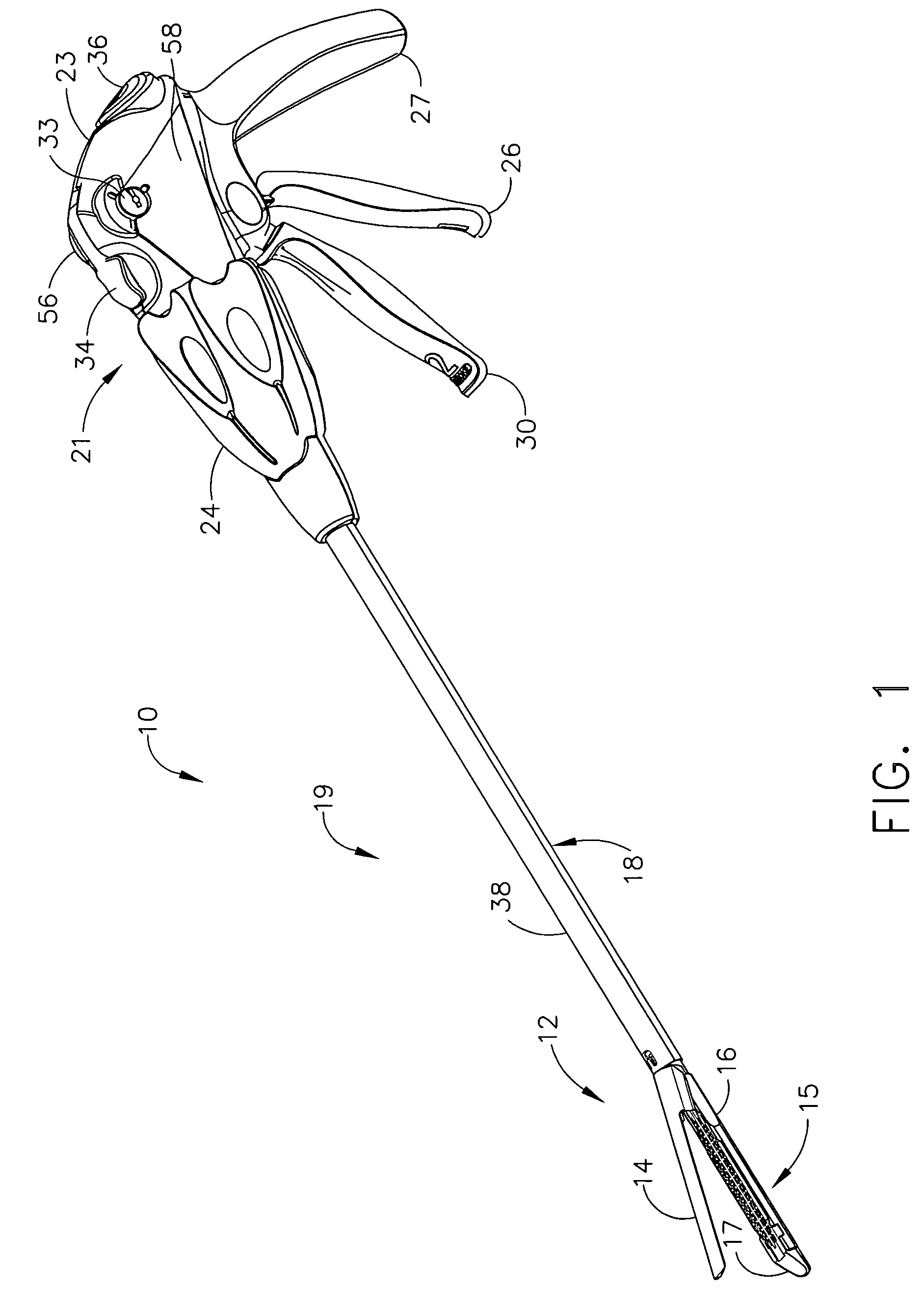
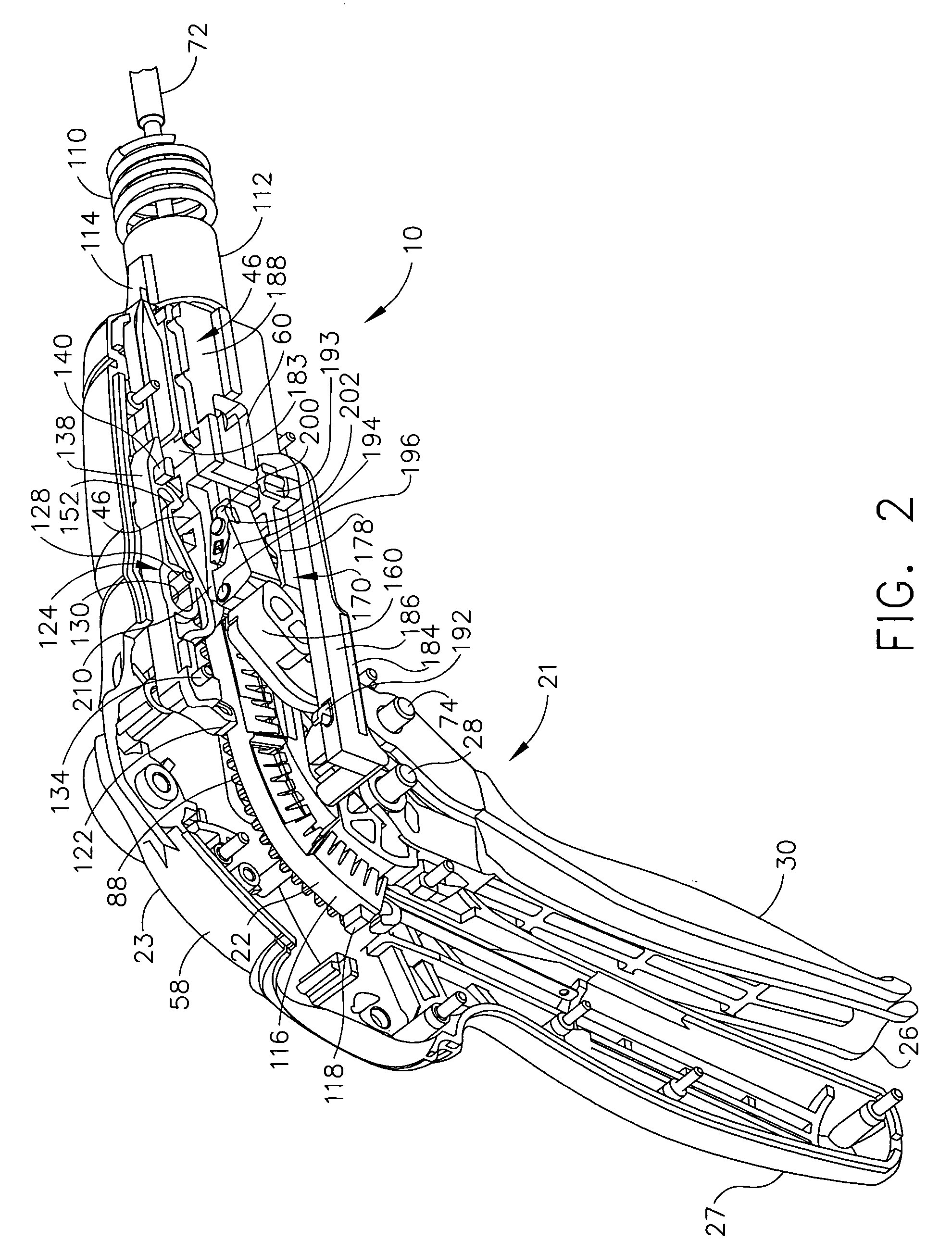
[0035]In FIG. 1, a surgical stapling and severing instrument 10 includes multi-stroke firing of an end effector, which in the illustrative version is a staple applying apparatus 12. An upper jaw (anvil) 14 may be repeatably opened and closed about its pivotal attachment to a lower jaw 15 of an elongate (staple) channel 16 engaged to a replaceable staple cartridge 17. The staple applying assembly 12 is proximally attached to elongate shaft 18, forming an implement portion 19. When the staple applying assembly 12 is closed, the implement portion 19 presents a small cross-sectional area suitable for insertion through a trocar by an externally connected and manipulated handle 21. In FIG. 2, a flexible firing rack 22 incorporated into the handle 21 advantageously transfers firing motion to the implement portion 19 yet retracts to enable a reduced length handle 21.

[0036]In FIGS. 1-3, the handle 21 has user controls mounted on its handle housing 23, such as a rotation knob 24 that rotates ...


PUM

PropertyMeasurementUnit
flexibleaaaaaaaaaa
areaaaaaaaaaaa
inner diameteraaaaaaaaaa

Abstract

A surgical stapling and severing instrument particularly suited to endoscopic procedures incorporates a handle that produces separate closing and firing motions to actuate an end effector. In particular, the handle produces multiple firing strokes in order to reduce the required amount of force required to fire (i.e., staple and sever) the end effector. A flexible rack transmits these firing strokes to a firing rod that reciprocates in an elongate shaft to actuate the end effector. The flexible rack advantageously stows into a pistol grip of the handle when retracted to minimize handle length.

Description

CROSS-REFERENCE TO RELATED APPLICATIONS[0001]The present application is a continuation in part of U.S. patent application Ser. No. 11 / 052,632, “MULTI-STROKE MECHANISM WITH AUTOMATED END OF STROKE RETRACTION” to Jeffrey S. Swayze et al., filed Feb. 7, 2005, now U.S. Pat No. 7,083,075 which in turn was a continuation in part of U.S. patent application Ser. No. 10 / 673,930 filed Sep. 29, 2003 entitled “SURGICAL STAPLING INSTRUMENT INCORPORATING A FIRING MECHANISM HAVING A LINKED RACK TRANSMISSION”, to Jeffrey S. Swayze, which issued as U.S. Pat. No. 6,905,057, the disclosures of both of which are hereby incorporated by reference in their entirety.FIELD OF THE INVENTION[0002]The present invention relates in general to surgical stapler instruments that are capable of applying lines of staples to tissue while cutting the tissue between those staple lines and, more particularly, to improvements relating to stapler instruments and improvements in processes for forming various components of s...

Claims


Application Information

Patent Timeline
Patent Type & Authority Patents(United States)
IPC IPC(8): A61B17/04
CPCA61B17/0682A61B17/07207A61B2017/320052A61B2017/2917A61B2017/2923A61B2017/2912
Inventor SHELTON, IV, FREDERICK E.
Owner CILAG GMBH INT
Learn More