
Lip light

a technology of illuminating devices and spherical plates, which is applied in piezoelectric/electrostrictive transducers, lighting support devices, lighting and heating apparatus, etc., can solve problems such as inability to see in the dark, blown out night vision goggles, and various gauges

Active Publication Date: 2007-12-04
CEJAY ENG
View PDF6 Cites 17 Cited by
  • Summary
  • Abstract
  • Description
  • Claims
  • Application Information

AI Technical Summary

Benefits of technology

[0007]The present invention extends the function, convenience and application beyond all other currently available lip lights. It allows the unit illumination to be actuated by either lip action or push button mode. Additionally, the present invention allows the brightness of the selected illumination to be changed using a potentiometer wheel. The present invention provides four LEDs which may all be switched on or off at the same time providing the best range of operating flexibility for the prevailing operating conditions. The present invention has a memory function which will bring the unit back into operation at its last used setting. The present invention's clamping system permits the invention to be easily attached to single or two boom microphone supports with a universal joint system which allows the invention light head to be easily positioned to suit each operator's personal needs.

Problems solved by technology

The reason for this is that the illuminating devices are so bright that the night vision goggles used would be blown out or otherwise adversely affected or compromised by the overloading of the illumination from the gauges.
Accordingly, an important problem for pilots and vehicle operators using a night vision system at night is that various gauges that must still be monitored during flight or vehicle operation cannot be seen in the dark.
Also, even if the night vision goggles are turned off or taken off, it is still imperative that the illumination of the gauges does not enable the aircraft or vehicle to be seen at night from outside the aircraft or vehicle when used clandestinely.

Method used


Image

  • Lip light
  • Lip light
  • Lip light

Examples


Embodiment Construction

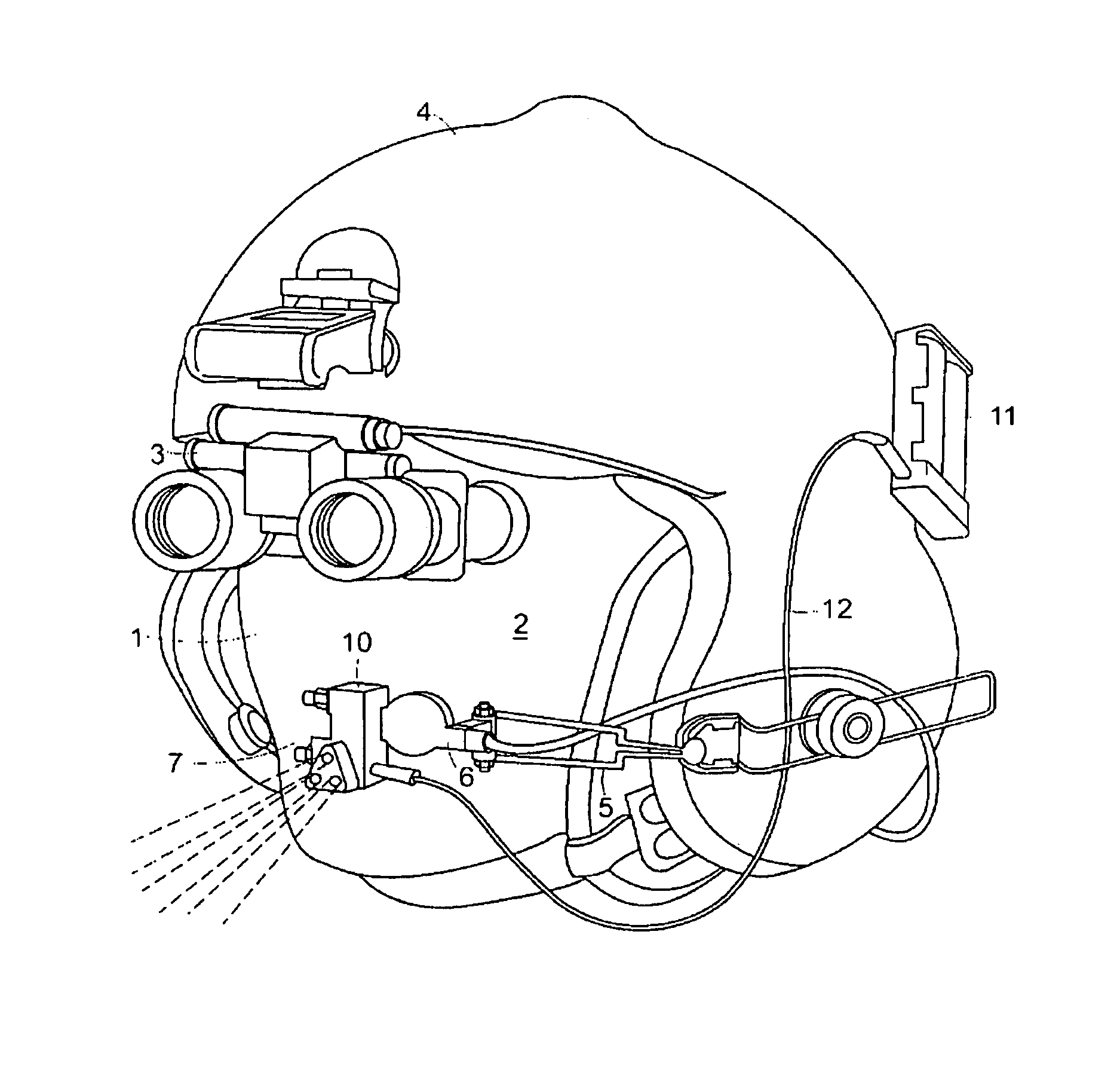
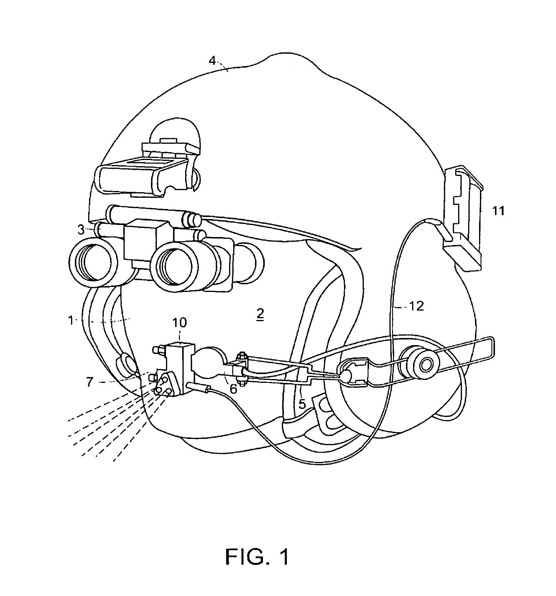
[0017]Referring to the drawings in detail wherein like elements are indicated by like numerals, there is shown a lip light 10 constructed according to the principles of the present invention. The lip light 10 is comprised of a light head 20 attached to a universal joint system 40 and interconnected by means of a wire 12 with a battery pack 11. The battery pack 11 may be conveniently removably attached to the helmet 4. The lip light 10 is attached to a microphone boom 5 attached to a helmet 4 worn by an operator 1. As may be best seen in FIG. 1, the operator 1 has night vision goggles 3 attached to his helmet 4 and positioned in front of his face 2. The microphone boom 5 is position so that a microphone 6 is positioned adjacent the operator's mouth area 7.

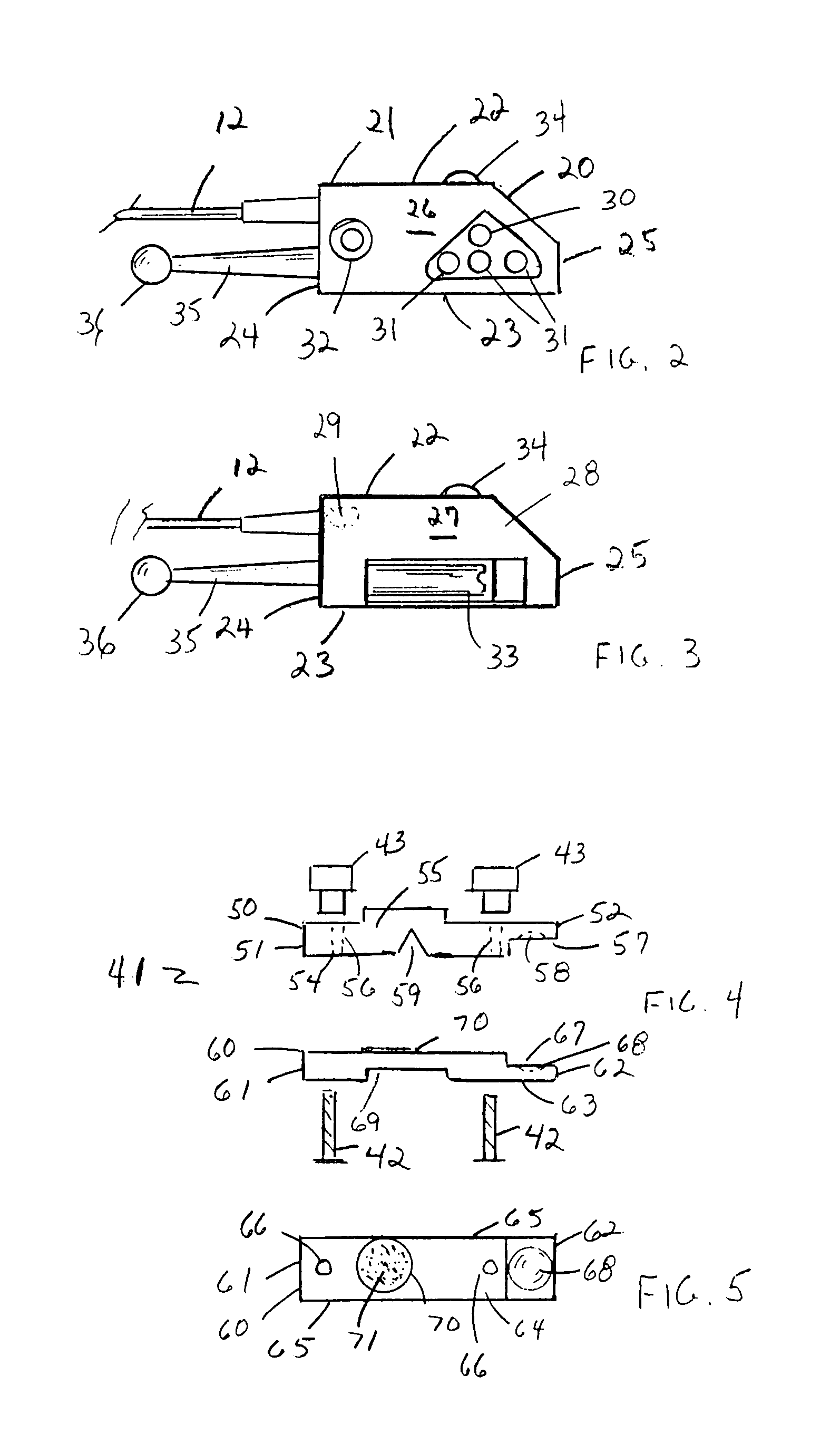
[0018]The light head 20 is comprised of a housing 21 having a nominal top 22, bottom 23, connection side 24, free side 25, front 26, rear 27, and exterior surface 28, said top, bottom, sides, front, and rear defining a housing inter...


PUM


Abstract

An illuminating device in combination with a microphone boom attached to a helmet worn by an operator. The illumination device is actuated by either lip action or push button. The brightness of the selected illumination is changeable by means of a potentiometer thumbwheel. The illumination device provides one spot and three flood light emitting diodes which may individually or as a group switched on or off. The illumination device has a universal clamping system permitting attachment to single or double boom microphone.

Description

CROSS-REFERENCE TO RELATED APPLICATIONS[0001]Applicants claim the priority benefits of U.S. Provisional Patent Application No. 60 / 665,194, filed Mar. 28, 2005.BACKGROUND OF THE INVENTION[0002]This invention relates to portable illuminating devices, and more particularly to a lip actuated illuminating device.[0003]There are presently on the market aviator's and military vehicle operator's night vision systems which enable pilots to fly helicopters or drive armored vehicles even in the darkest of night conditions without illumination. However, in order to be able to use the available night vision systems it is necessary to turn off the illuminating means for the various gauges used in the cockpit of a helicopter or vehicle. The reason for this is that the illuminating devices are so bright that the night vision goggles used would be blown out or otherwise adversely affected or compromised by the overloading of the illumination from the gauges. That is, the illumination from the gauges...

Claims


Application Information

Patent Timeline
Patent Type & Authority Patents(United States)
IPC IPC(8): F21V21/084
CPCH05B33/0842H05B33/0803A61F9/029H05B45/00
Inventor HAYNES, DEREKJENKINS, STUART M.
Owner CEJAY ENG
Learn More