
Pen adapted to be pressurized

a pen and pressurized technology, applied in the field of pen, can solve the problems of ink leakage, inability to smoothly outflow, and easily contaminate the pen holder, so as to prevent leakage of the medium, facilitate deformation, and ensure smooth supply

Inactive Publication Date: 2007-12-04
TOMBOW PENCIL CO LTD
View PDF1 Cites 9 Cited by
  • Summary
  • Abstract
  • Description
  • Claims
  • Application Information

AI Technical Summary

Benefits of technology

[0007]An object of the invention is to provide an improved pressurization pen. More specifically it is an object of the invention to provide a pressurization pen capable of being manufactured with low cost, with which a medium such as ink, a correction fluid, a paste can be smoothly supplied and an excessive pressurization within a tube accommodating the medium and a leakage of the medium can be prevented. Still another object of the invention is to provide a pressurization pen which can be easily used in a state that a pen tip is directed upwardly.
[0020]Since the inside of the ink accommodating tube is pressurized and subsequently ventilated to the ambient air through a single push and release operation of the pressing unit, the medium like ink etc. can be smoothly supplied and an excessive pressurization within the medium accommodating tube and leakage of the medium be prevented. Furthermore the pen can be used in a state that the pen tip is directed upwardly. Since an elastic body which can easily be deformed is used, a specific manufacturing precision is not required so that it is possible to manufacture the pen with low costs. The elastic body preferably is formed as spherical body. Thereby it is deformed elastically upon pressurizing to be pushed into the pressurizing chamber and the pressurization can be smoothly performed and the elastic deformation in an axial direction is relatively large. Therefore, the pressurization by a single stroke pushing of the pressing unit becomes larger and the pressurization efficiency can be increased. Since the rear end of the axial housing is covered with the cap in use of the pen to easily maintain the pressurized state, it is effective particularly in preventing the interruption of ink when the pen is used in a state that the pen tip is directed upwardly.
[0021]Since the pressing unit is automatically pushed by the pushing operation of the knock stem in use of the pen to maintain the pressurized state, it is effective particularly in preventing the interruption of ink when the pen is used in a state that the pen tip is directed upwardly.

Problems solved by technology

The known pen, for example, a ballpoint pen has been experienced a disadvantage that ink does not smoothly outflow from a pen tip of a pen refill unit in use or ink is interrupted during writing, so that when such problem is occurred, it is necessary to scrub the pen tip on a paper to outflow the ink.
In this state, when the pressurizing pump mechanism is repeatedly operated, the inside of the ink accommodating tube becomes an excessive pressurized state so that the ink leakage may easily occur to contaminate a pen holder, and hence hands or clothes.
In addition, there is further disadvantage that in order to maintain the inside of the ink accommodating tube in a high airtight state, materials of seal parts and the processing precision are required, thereby increasing a cost.

Method used


Image

  • Pen adapted to be pressurized
  • Pen adapted to be pressurized
  • Pen adapted to be pressurized

Examples


first embodiment

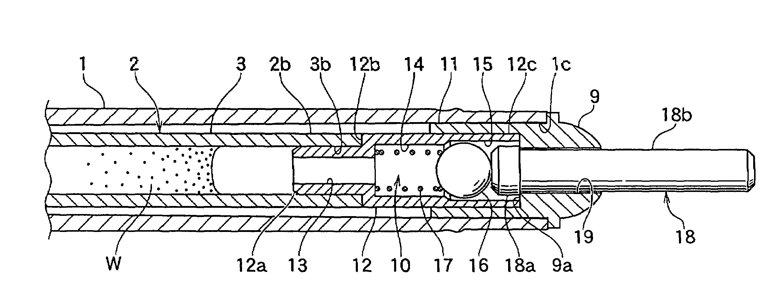
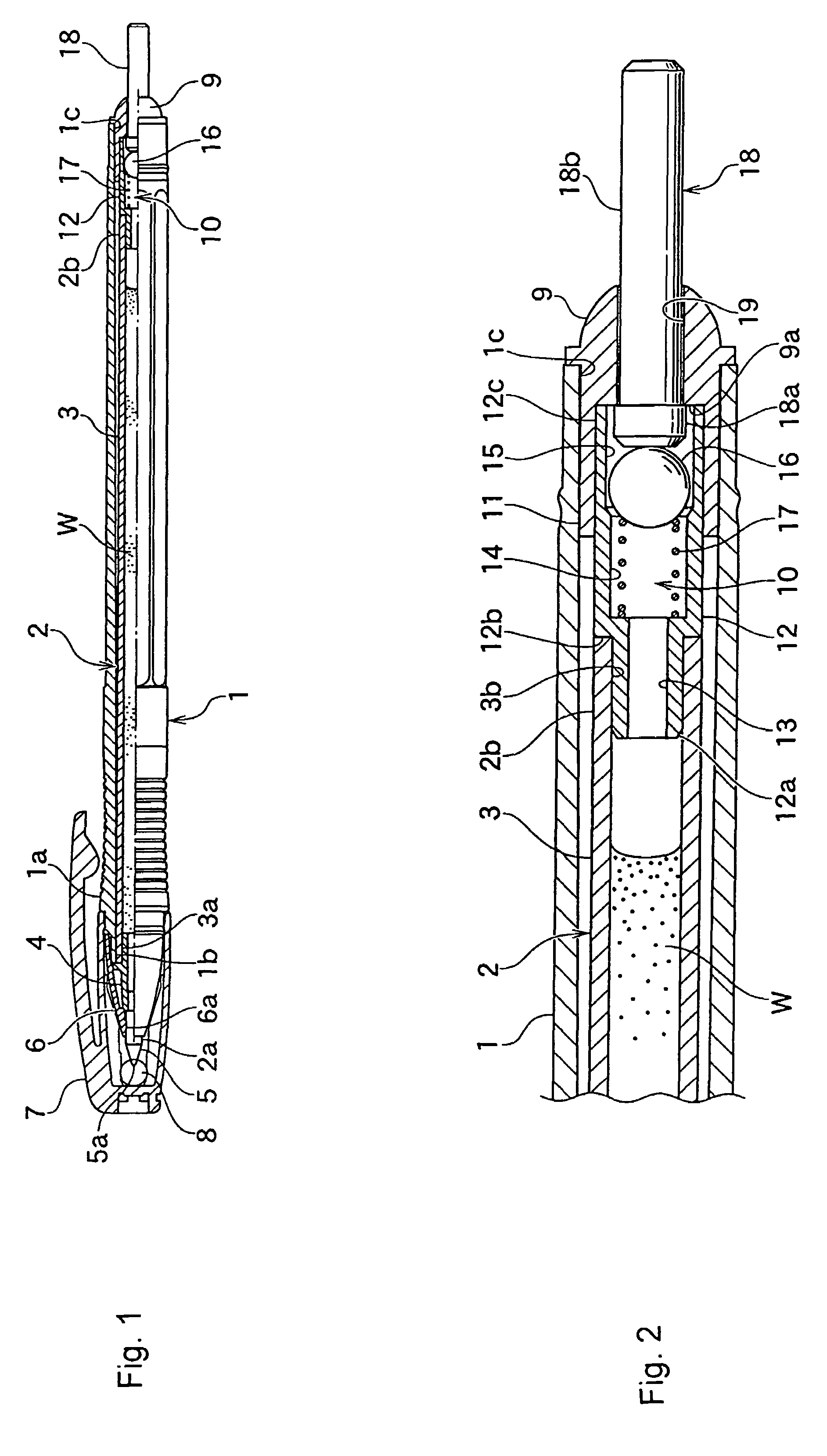
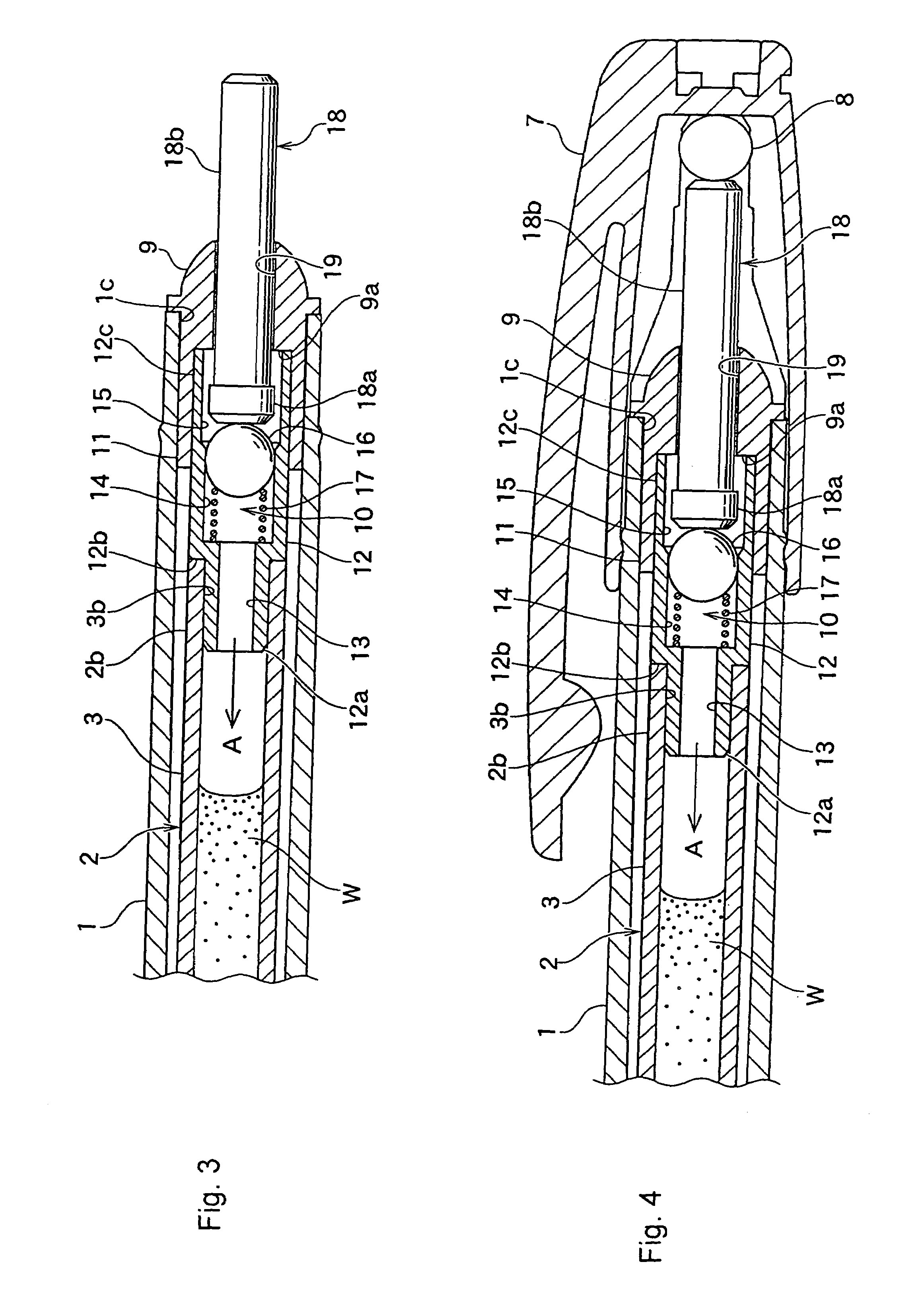
[0029]Hereinafter, preferred embodiments of the invention will be described in detail with respect to a ballpoint pen as an example. FIG. 1 is a half cross sectional view illustrating a pressurization pen according to the invention. FIG. 2 is an enlarged cross sectional view of main parts illustrating a pressurizing pump mechanism in a non-pressurized state when the pen is not used. FIG. 3 is an enlarged cross sectional view of main parts in a pressurized state when the pen is used. In the figures, with respect to a paper, ‘left side’ is referred to as ‘front’ and ‘right side’ is referred to as ‘rear’.

[0030]As shown in FIG. 1, a ballpoint pen in accordance with of the first embodiment of the invention has an axial housing 1, and a pen refill unit 2 mounted within the axial housing 2 in a fixed state. The pen refill unit 2 includes an ink accommodating tube 3 having ink W filled therein as a writing medium, and a pen tip 5 mounted at a front end 3a of the ink accommodating tube 3 by ...

second embodiment

[0040]FIGS. 5 and 6 are enlarged cross sectional views of main parts of the invention. This embodiment has a pressurizing pump mechanism 20 incorporated in a knock type ballpoint pen. The knock type ballpoint pen has a known knock mechanism with which a pen tip (not shown) of a pen refill unit 21 can be projected and retracted, and the detailed explanation thereof will be omitted.

[0041]As shown in FIG. 5, a knock mechanism 23 is provided in a rear end opening 22a of an axial housing 22. The knock mechanism 23 is a known mechanism in which a knock stem 24 provided in the rear end opening 22a of the axial housing 22 performs push and release operations against the urging force of a compression spring 25 to drive a rotator 27 by a cam mechanism 26, so that the pen tip of the pen refill unit 21 can be projected to protruded state and retracted to the accommodated state.

[0042]A pressing chess-piece body 28 corresponding to the pressing stem 18 of the pressurizing pump mechanism 10 in the...


PUM


Abstract

a pen adapted to be pressurized and capable of being manufactured inexpensively, with which ink can be smoothly supplied and an excessive pressurization within an ink accommodating tube and the leakage of ink can be prevented, as well as a pen that can be easily used in a state that a pen tip is directed upwardly. The pen comprises a pressurizing pump mechanism 10 which pressurizes an inside of ink accommodating tube 3 and includes a pressurizing chamber 14 communicating with the inside of the ink accommodating tube, an elastic spherical body 16 disposed to be pushed into the pressurizing chamber, a compression spring 17 that urges the spherical body in a direction to be released from within the pressurizing chamber, and a pressing stem 18 that moves the spherical body against the urging force of the compression spring into the pressurizing chamber in an airtight state.

Description

BACKGROUND OF THE INVENTION[0001]1. Field of the Invention[0002]The present invention relates to a pen, for example, a ballpoint pen, a correction pen, a sizing pen, and particularly to a pen adapted to be pressurized (hereinafter pressurization pen), which is capable of smoothly supplying a medium such as ink, correction fluid, paste, etc., when using the pen.[0003]2. Description of the Related Art[0004]The known pen, for example, a ballpoint pen has been experienced a disadvantage that ink does not smoothly outflow from a pen tip of a pen refill unit in use or ink is interrupted during writing, so that when such problem is occurred, it is necessary to scrub the pen tip on a paper to outflow the ink.[0005]To overcome such disadvantage, as disclosed in Japanese Patent Publication JP-A-2004-268567 (FIGS. 3 and 4) and Japanese Patent Publication JP-A-2005-178304 (FIGS. 3 and 4), it has been suggested that a pen refill unit of a ballpoint pen is provided with a pressurizing pump mechan...

Claims


Application Information

Patent Timeline
Patent Type & Authority Patents(United States)
IPC IPC(8): A46B11/02
CPCB43K7/03B43K7/12B43K23/126B43L19/0068B43K25/022B43L19/0018B43K24/08B43K5/00B43L19/00B43K8/02
Inventor MURAKOSHI, YASUO
Owner TOMBOW PENCIL CO LTD
Learn More