Adaptive method used to overcome channel to channel isolation

a channel isolation and adaptive technology, applied in the direction of resistance/reactance/impedence, instruments, measurement devices, etc., can solve the problems of inherently high isolation cost, more) measurement channels of the vna to be designed with inherently high isolation, and achieve the effect of reducing isolation requirements

Inactive Publication Date: 2007-12-04
ANRITSU CO
View PDF1 Cites 21 Cited by
  • Summary
  • Abstract
  • Description
  • Claims
  • Application Information

AI Technical Summary

Benefits of technology

[0037]Attenuation in the reference channel is removed or deleted when the signal in the test channel is sufficient to overcome the leakage of the reference channel. Additionally, attenuation is removed from the test channel when the reference channel has the high attenuation inserted to further increase the difference between the leakage reference signal and the reduced test channel signal thus allowing lower isolation requirements on the two (or more) receiving channels. The embodiments of the present invention can be either mixer or sampler based in construction.

Problems solved by technology

The resulting constructive and destructive addition of the desired measurement signal through the DUT causes a ripple signal to appear.
A limitation is reached when the reference signal is decreased enough to cause noticeable noise when measuring low insertion loss devices due to the excess noise in the reference channel itself.
This forces the two (or more) measurement channels of the VNA to be designed with inherently high isolation at a considerable cost.
The relative merits of mixer vs. sampler based systems is primarily due to complexity of the mixer, although LO frequency generation is also more complex in mixers.
These devices rely on very complex splitters.
The drawback to this technique is that the KTB noise of the reference channel dominates in low loss measurements.

Method used


Image

  • Adaptive method used to overcome channel to channel isolation
  • Adaptive method used to overcome channel to channel isolation
  • Adaptive method used to overcome channel to channel isolation

Examples


first embodiment

1. First Embodiment

[0057]In a first embodiment of the present invention, A1 is changed to allow T / R1=R / NSR+Delta instead of T / R1+T / NST+Delta. One advantage that this provides is to allow the noise due to Rns to be at a minimum for DUT=45.4 dB. The equations for A1 and A2 are rederived as follows:

T / R1=R / NSR+Delta

T−R1=R−NSR+Delta

R1=R−ISO

T−R+ISO=R−NSR+Delta

T+ISO=2*R−NSR+Delta

2*R=T+ISO−NSR−Delta

R=(T+ISO+NSR−Delta) / 2

R=PIN−CPL−A1 (Determined From FIG. 4)

PIN−CPL−A1=(T+ISO+NSR−Delta) / 2 (By setting R=R in last 2 equations)

A1=PIN−CPL−(T+ISO+NSR−Delta) / 2

A1=PIN−CPL−PIN / 2+(IL+DUT+A2+Delta−ISO−NSR) / 2

A1=PIN / 2−CPL+(IL+DUT+A2+Delta−ISO−NSR) / 2  (Equation 2 for A1)

[0058]Applying the values from the previous, non-limiting example of NFR=NFT=29 dB, BWR=BWT=23 KHZ, NSR=101.4 dBm, PIN=9 dBm, IL=4 dB, CPL=14 dB, ISO=50 dB and Delta=+15 dB we determine A1 as follows:

A1=PIN / 2−CPL+(IL+DUT+A2+Delta−ISO−NSR) / 2  (From Equation 2 for A1)

A1=+9 / 2−1 4+(+4+DUT+26+15+50−(−101.4) / 2

A1=DUT / 2+38.7

[0059]This equation shows...

second embodiment

2. Second Embodiment

[0063]In a second embodiment of the present invention, a slight reduction in total noise can be realized if conditions are reverted back to T / R1=T / NST+Delta for DUT>45.4 dB. The noise reduction occurs where Tns=Rns at DUT=45.4 dB.

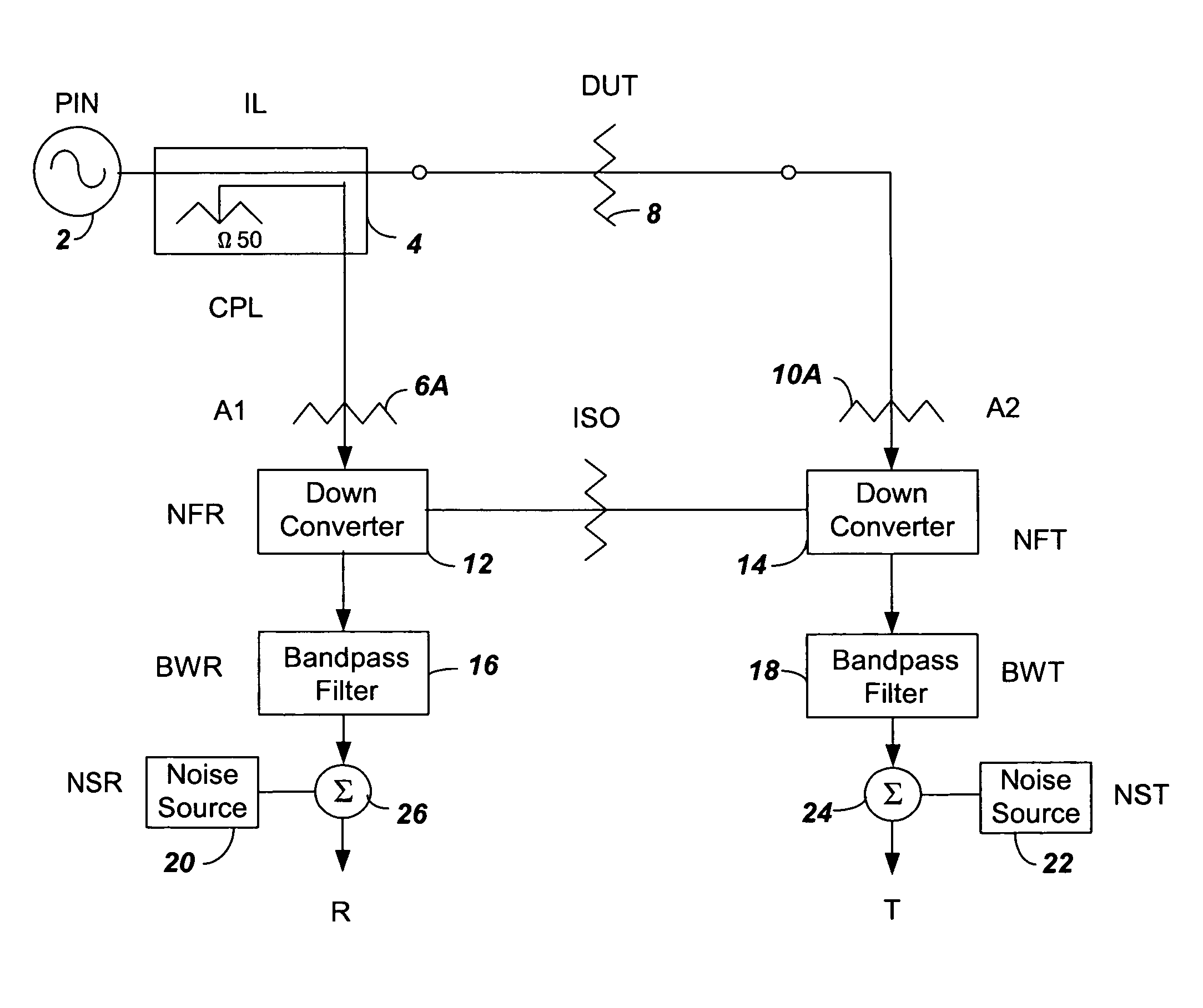
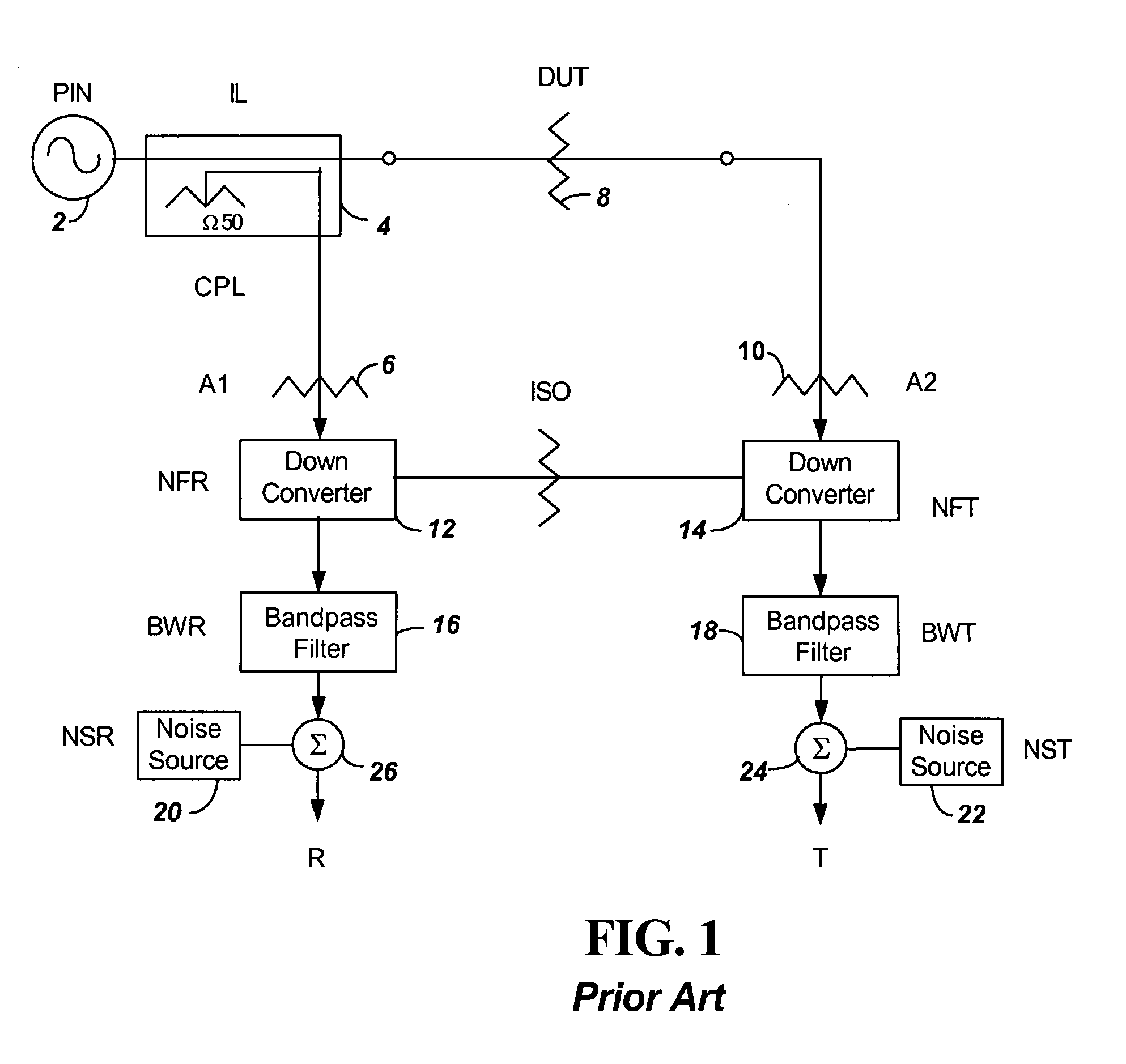
[0064]FIG. 7 shows a plot of S / N ratio in dB for three different signals for three different measured signals versus DUT loss in dB with A1 being a variable attenuator that tracks the DUT value only up until DUT=45.4 dB. First, a plot 700 of the reference channel signal to noise ratio R / NSR is provided vs. DUT loss. Second, a plot 702 of the test channel signal to noise ratio T / NST is provided vs. DUT loss. Third a plot 704 of the test channel signal to interfering signal T / RI is provided vs. DUT loss.

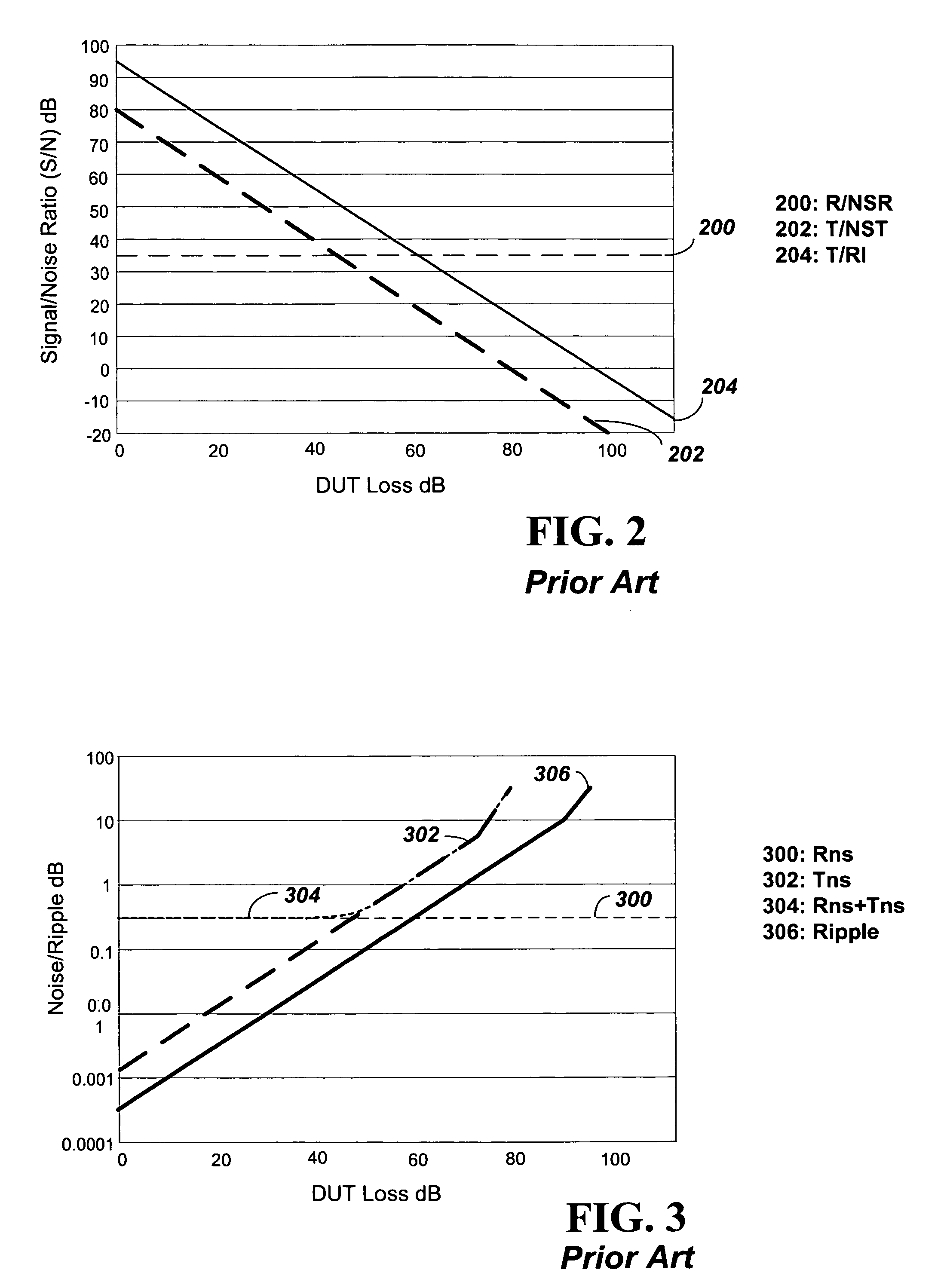
[0065]FIG. 8 shows a plot of converted noise signals and ripple versus DUT loss in dB with the variable A1 attenuator that tracks the DUT loss. First, a plot 800 of the converted reference channel S / N Rns is provided vs. DUT loss. Second, a...

third embodiment

3. Third Embodiment

[0067]For a further embodiment of the present invention, the value of A2 is altered to create a greater dynamic range for the VNA. The value of A2 in previous embodiments described has been fixed due to the fact that a given maximum input to the test channel down converter of −21 dBm and given that T=PIN−IL−DUT−A2 forces A2 to be PIN−IL−DUT+21. For the minimum value of DUT of 0, this forces A2 to be +9−4−0+21=26 dB. If A2 is allowed to go from 26 dB to 0 dB when the DUT goes from 0 dB to 26 dB, then the maximum input of the test channel would satisfy the maximum input of −21 dBm. This provides the benefit of an increase of 26 dB of dynamic range. With A2 modified as described, the equations for A1 and A2 are changed as follows:

A2=PIN−IL−DUT−T  (From Equation 1 for A2)

A2=PIN−IL−DUT+21 (With T=−21 dBm under the new conditions)

A1=PIN / 2−CPL+(IL+DUT+A2+Delta−ISO−NSR) / 2  (From Equation 2 for A1)

A1=PIN / 2−CPL+(IL+DUT+(PIN−IL−DUT+21)+Delta−ISO−NSR) / 2 (by substituting A2)

A1...


PUM


Abstract

Selectable attenuators are used in the reference and test paths of a VNA, with attenuation automatically inserted or deleted when the Device Under Test (DUT) attenuation reaches predetermined thresholds. Attenuation in the reference channel is removed when the signal in the test channel is sufficient to overcome the leakage of the reference channel. Additionally, attenuation is removed from the test channel when the reference channel has a high attenuation inserted to further increase the difference between the leakage reference signal and the reduced test channel signal thus allowing lower isolation requirements on the two (or more) receiving channels.

Description

BACKGROUND[0001]1. Technical Field[0002]The present invention relates to providing attenuation in a Vector Network Analyzer (VNA) receiver to prevent non-linear receiver signal output when measuring insertion loss or gain of a device under test (DUT).[0003]2. Related Art[0004]Currently available two port VNAs attenuate the reference channel as much as practical to overcome the leakage signal from the reference channel to the test channel. The resulting constructive and destructive addition of the desired measurement signal through the DUT causes a ripple signal to appear. A limitation is reached when the reference signal is decreased enough to cause noticeable noise when measuring low insertion loss devices due to the excess noise in the reference channel itself. This forces the two (or more) measurement channels of the VNA to be designed with inherently high isolation at a considerable cost.[0005]Due to these high noise isolation requirements, the design of a combined source and de...

Claims


Application Information

Patent Timeline
Patent Type & Authority Patents(United States)
IPC IPC(8): G01R23/16
CPCG01R27/28
Inventor BRADLEY, DONALD ANTHONY
Owner ANRITSU CO
Why Eureka
Try Eureka