Method for audibly measuring optical efficiency in an installed fiber optic link

a fiber optic link and optical transmission technology, applied in the field of fiber optics, can solve the problems of unsuitable laboratory use, cable b>10/b> damage, and inability to meet the requirements of laboratory use, and achieve optimal transmission efficiency, optical connection optimization, and optical transmission efficiency.

Inactive Publication Date: 2005-03-01
THE BOEING CO
View PDF16 Cites 18 Cited by
  • Summary
  • Abstract
  • Description
  • Claims
  • Application Information

AI Technical Summary

Benefits of technology

The present invention overcomes the deficiencies of the prior art by providing a method for optimizing the optical transmission efficiency of a fiber optic connection without having to disconnect the fiber optic connections. The method comprises providing a transmitter that produces a signal that is degraded following transmission through two coupled fiber optic cables that are to be optimized. The received signal is processed by a clock recovery circuit, a lowpass filter, and a retiming circuit. The clock recovery circuit obtains a recovered clock signal and the lowpass filter filters and delays recovered data transmitted through the fiber optic connection. A sampling comparator, such as the industry standard AM685 microcircuit, digitizes and retimes the recovered data signal from the lowpass filter using the recovered clock signal from the clock recovery circuit. The variable delay of the lowpass filter is used to adjust the retiming to a less than optimal delay value as a means of introducing a controlled error rate. The output of the sampling comparator represents a degraded signal having errors that can be analyzed by the bit error rate subsystem. The bit error rate subsystem produces error pulses that are subsequently converted to audible sounds. The frequencies present in the sounds are representative of and proportional to the rate of data transmission errors. Optimal transmission efficiency is determined by manipulating the cables, and their associated ferrules, until the error signals occur least frequently and the audio frequencies are lowest, thus indicating that the optical connection is optimized. Thus, the present invention provides a method for introducing errors into a digital fiber optic communication link so that small analog changes in optical transmission efficiency can be determined by changes in the audible error rate.

Problems solved by technology

Consequently the method is only suitable for laboratory use and not for field use because removing cables 10 will likely cause the cables 10 to be damaged due to the infiltration of foreign materials.
Specifically, in stressful repair scenarios, such as on an aircraft carrier deck, the cables 10 may be damaged by salt spray, grease, or other substances harmful to optical fibers.

Method used


Image

  • Method for audibly measuring optical efficiency in an installed fiber optic link
  • Method for audibly measuring optical efficiency in an installed fiber optic link
  • Method for audibly measuring optical efficiency in an installed fiber optic link

Examples


Embodiment Construction

The following description of the preferred embodiment is merely exemplary in nature and is in no way intended to limit the invention, its application, or uses.

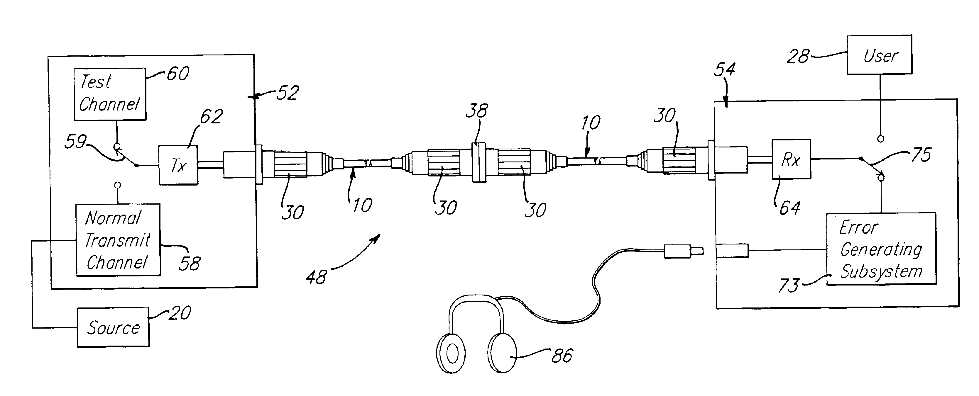
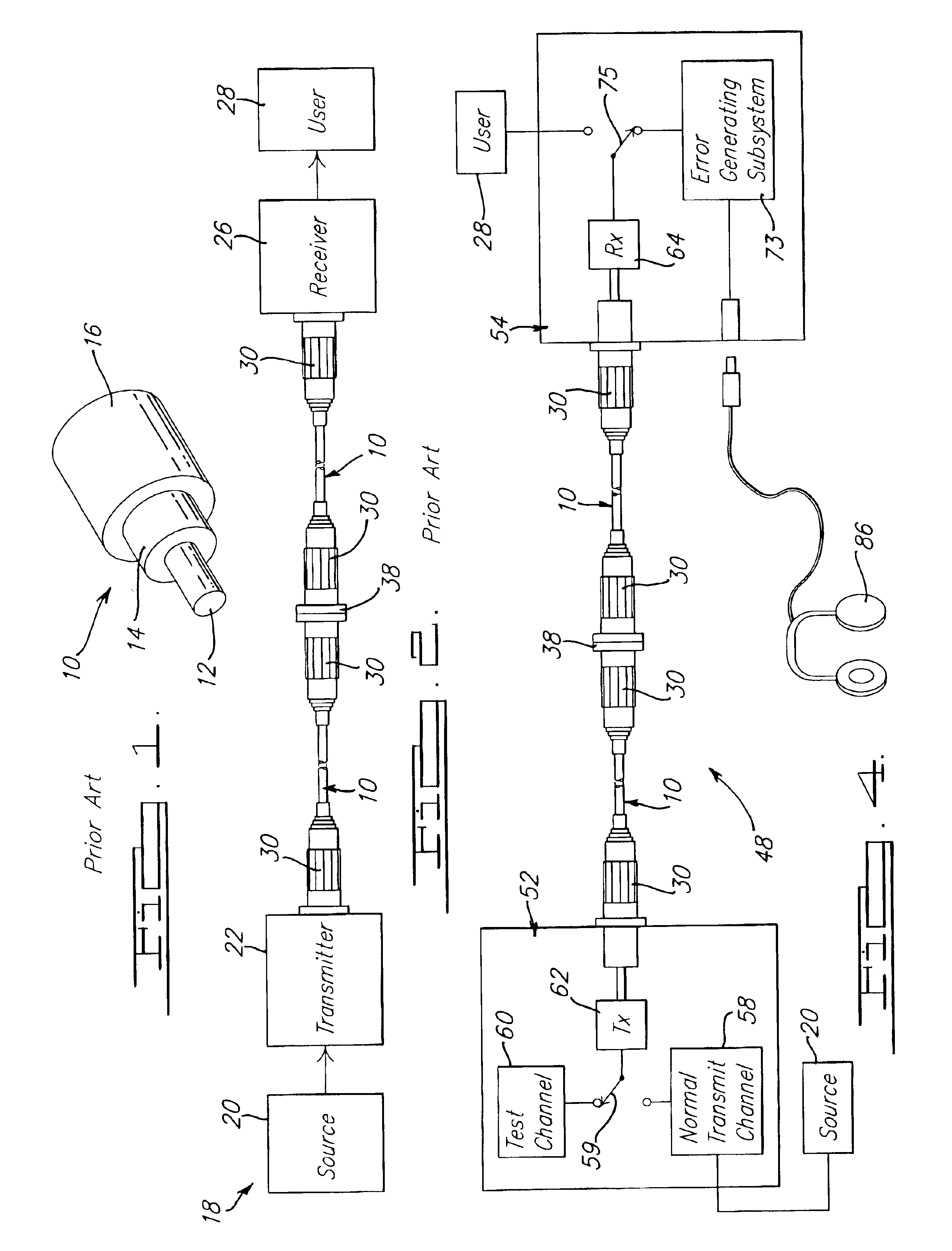
The present invention, in one preferred embodiment, relates to a data link 48 as shown in FIG. 4. The data link 48 generally includes a source 20, a transmitter 52, and a receiver 54. A user 28 receives an output of the receiver 54. The transmitter 52 is generally comprised of a normal transmit channel 58, a test channel 60, and a fiber optic transmitter (e.g. laser or LED) 62. The receiver 54 is generally comprised of a fiber optic receiver 64 and an error generating subsystem 73.

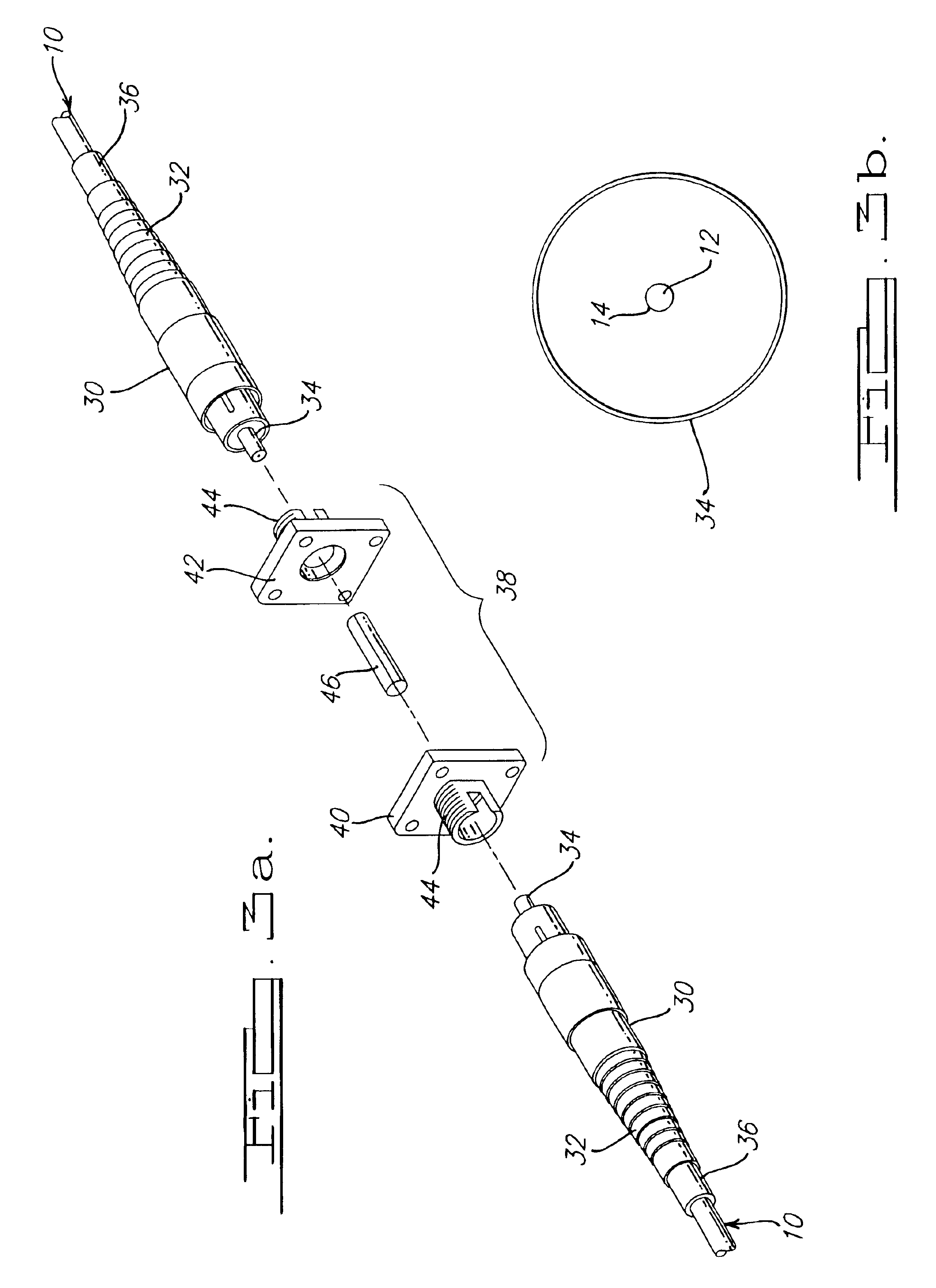
The fiber optic cables 10 are connected by connectors 30 using any suitable method or device, such as housing 38 and alignment sleeve 46, in the conventional manner. The data link 48 provides analog signal measurement to enable the user 28 to audibly adjust the coupling of the optical cables 10 to maximize the efficiency of the coupling thereof. Whil...


PUM


Abstract

A method for introducing errors into a digital fiber optic communication link so that small analog changes in optical transmission efficiency can be determined by changes in the audible error rate. The method comprises providing a transmitter with a test channel that provides a pseudorandom encoded optical transmission through coupled fiber optic cables. The signal is sent through the cables and received by a receiver which introduces and measures errors. The received signal is split and processed by a clock recovery circuit and a lowpass filter. The clock recovery circuit obtains the optimal sampling point. The lowpass filter filters the data and provides a timing adjustment relative to the recovered clock signal. The clock retimes the filtered data with a sampling comparator. The variable timing introduces errors allowing optical transmission efficiency measurements. A bit error rate tester produces audible sounds whose frequency content is related to the bit error rate. Optimal transmission efficiency is determined by manipulating the cables and their associated ferrules until the audible sounds have the lowest frequencies.

Description

FIELD OF THE INVENTIONThe present invention generally relates to fiber optics. In particular, the present invention relates to a method for determining the optical transmission quality of an installed fiber optic link.BACKGROUND OF THE INVENTIONFiber optic cable is a common type of cabling used to transmit optical data from one location to another. Fiber optic cable is generally comprised of either glass, a combination of glass and polymers, or just polymers (plastic optical fibers). Fiber optic cable is fabricated in such a way that it can conduct a beam of light from one end of the cable to another.A typical fiber optic cable 10 is illustrated in FIG. 1. As seen in FIG. 1, fiber optic cable 10 is generally comprised of a core 12, cladding 14, and buffer / outer jacket 16. The core 12 is a very narrow strand of high quality glass and is carried through the cable 10 by way of the cladding 14. The cladding 14 is also made of high quality glass but has a slightly lower index of refracti...

Claims


Application Information

Patent Timeline
Patent Type & Authority Patents(United States)
IPC IPC(8): H04B10/08G02B6/38
CPCH04B10/07G02B6/3807G02B6/3874G02B6/3825
Inventor HARRES, DANIEL N.GREEN, SAMUEL I.
Owner THE BOEING CO
Why Eureka
Try Eureka