Method of positioning disk-shaped medium

a technology of disk-shaped media and positioning method, which is applied in the direction of mechanical energy handling, record information storage, instruments, etc., can solve the problems of inability to absorb clearance, inability to use conventional hubs, and inability to achieve correct positioning

Inactive Publication Date: 2007-12-04
KK TOSHIBA
View PDF6 Cites 10 Cited by
  • Summary
  • Abstract
  • Description
  • Claims
  • Application Information

AI Technical Summary

Benefits of technology

[0018]By using the method of the present invention, the center of the disk-shaped medium can be correctly positioned with respect to the rotary shaft of the motor, etc. The method can be effectively used for setting the disk-shaped medium or media in a devic

Problems solved by technology

However, if manufacturing accuracy of the disk-shaped media 10 is much lower than that of other members, the clearances cannot be absorbed.
In the case of using a plurality of types of the disk-shaped media, inner diameters of the center holes are not fixed, so the conventional hub cannot be used.
However, preparing the ne

Method used


Image

  • Method of positioning disk-shaped medium
  • Method of positioning disk-shaped medium
  • Method of positioning disk-shaped medium

Examples


Embodiment Construction

[0025]Preferred embodiments of the present invention will now be described in detail with reference to the accompanying drawings.

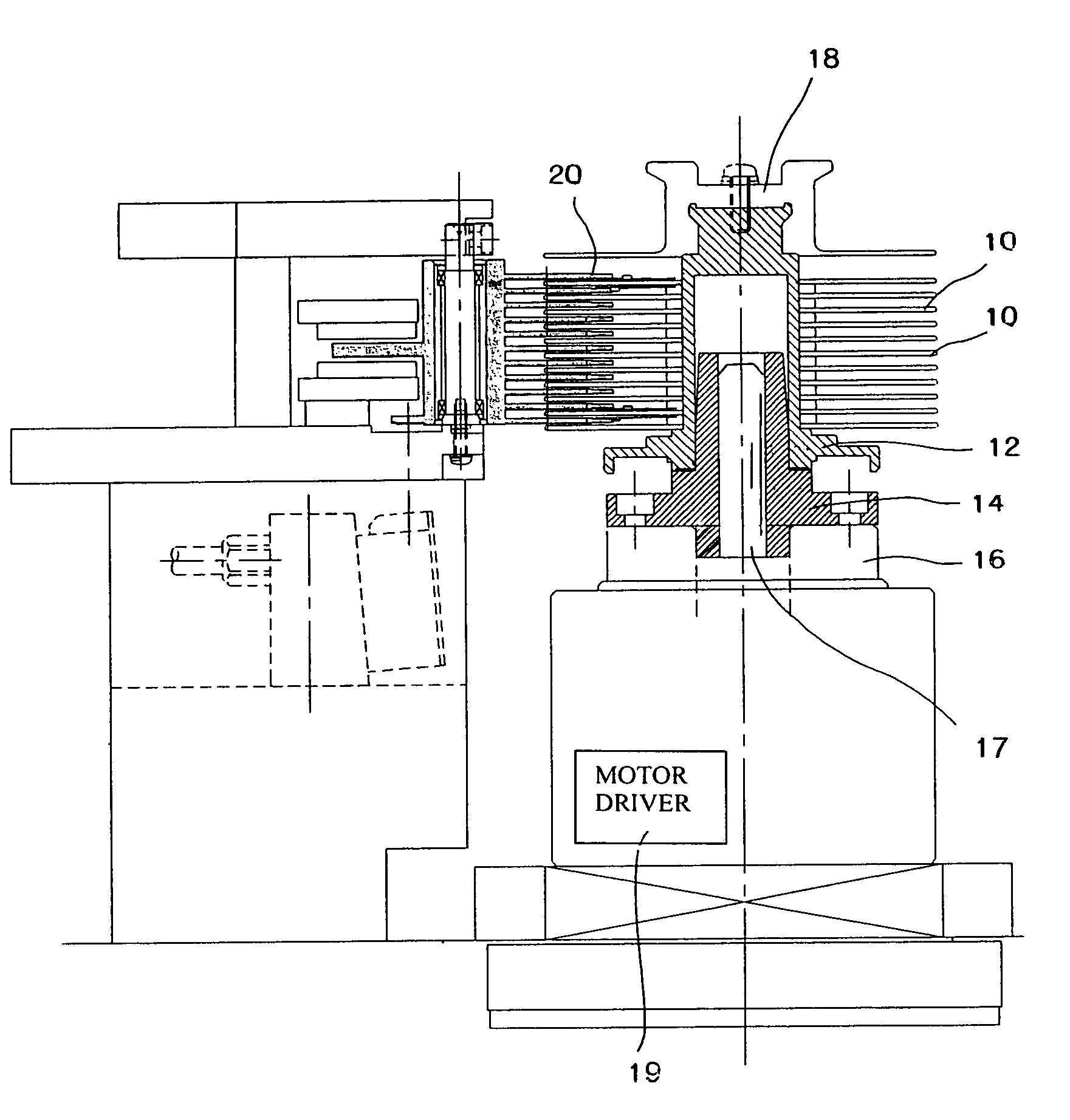
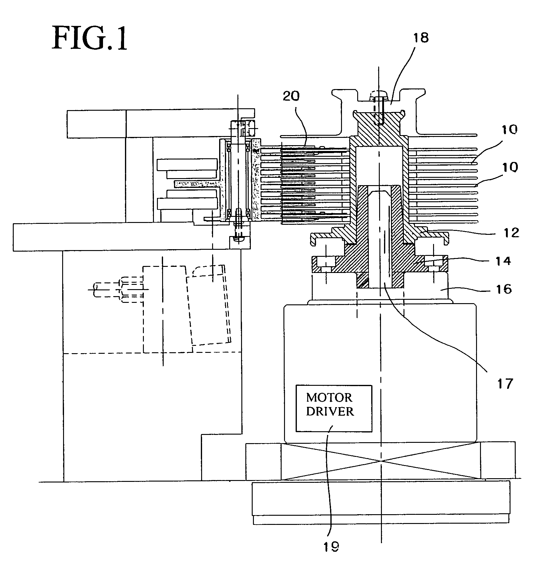
[0026]In FIG. 1, a plurality of disk-shaped media 10 are set in a servo track writer. The disk-shaped media 10 are correctly positioned by the method of the present invention. The disk-shaped media 10 are held by a hub 12. The hub 12 is inserted in center holes of the disk-shaped media 10. The disk-shaped media 10 are piled with spacers. By the spacers, the adjacent disk-shaped media 10 are separated with a predetermined separation. The disk-shaped media 10, which have been attached to the hub 12, is biased toward the hub 12 so as to make an inner face of the center hole of the disk-shaped media 10 contact with an outer face of the hub 12, so that the disk-shaped media 10 are eccentrically positioned with respect to the hub 12. A fixing member 18 is fixed on a top part of the hub 12 by a screw so as to eccentrically hold the disk-shaped media 10 with respe...


PUM

PropertyMeasurementUnit
Angleaaaaaaaaaa

Abstract

The method of positioning a disk-shaped medium is capable of precisely positioning the center of the disk-shape medium with respect to a center of a rotary shaft. The method comprises the steps of: inserting a cylindrical hub into a center hole of the disk-shaped medium; and covering a hub adaptor, which is eccentrically fixed to a rotary shaft, with the hub so as to position the disk-shaped medium on the rotary shaft. Directions of eccentricity of the disk-shaped medium, the hub and a hub unit are defined on the basis of amount of eccentricity between the disk-shaped medium and the hub, that between the hub and the hub adaptor and that between the hub adaptor and the rotary shaft.

Description

BACKGROUND OF THE INVENTION[0001]The present invention relates to a method of positioning a disk-shaped medium, which is capable of precisely positioning the disk-shaped medium on a rotary shaft.[0002]A conventional method will be explained with reference to FIGS. 5A and 5B. FIG. 5A is an explanation view (a plan view) of a servo track writer and FIG. 5B is an explanation view (a sectional view) thereof, in each of which a plurality of disk-shaped media 10 have been set. A plurality of disk-shaped media 10 are piled to cover a hub 12 with regular separations and arranged in the axial direction of the hub 12. The hub 12 is connected to a motor 16 with a hub adaptor 14, and the hub 12 is rotated by the motor 16. With this structure, servo track data can be written on the disk-shaped media 10 by a writing head of a recording apparatus.[0003]In the apparatus for writing servo track data on the disk-shaped media 10 which have been attached to the hub 12, centers of the disk-shaped media ...

Claims


Application Information

Patent Timeline
IPC IPC(8): G11B17/02G11B5/012G11B19/20G11B17/038G11B25/04H02K7/00H02K15/00
CPCG11B17/038G11B25/043H02K15/00H02K7/003Y10T29/49025Y10T29/49009
Inventor KATO, TOSHIYAARAI, TERUSHIGEFUKUSHI, MASANORI
Owner KK TOSHIBA
Why Eureka
Try Eureka