Method, system, and product for isolating memory system defects to a particular memory system component

a memory system and component technology, applied in the field of data processing systems, can solve the problems of inability to test the exact difficulty in identifying exact components, and prior art method that does not elaborately test the memory card component of the memory system and the logic around

Inactive Publication Date: 2007-12-04
INT BUSINESS MASCH CORP
View PDF3 Cites 33 Cited by
  • Summary
  • Abstract
  • Description
  • Claims
  • Application Information

AI Technical Summary

Benefits of technology

[0008]The above as well as additional objectives, features, and advantages of the present invention will become apparent in the following detailed written description.

Problems solved by technology

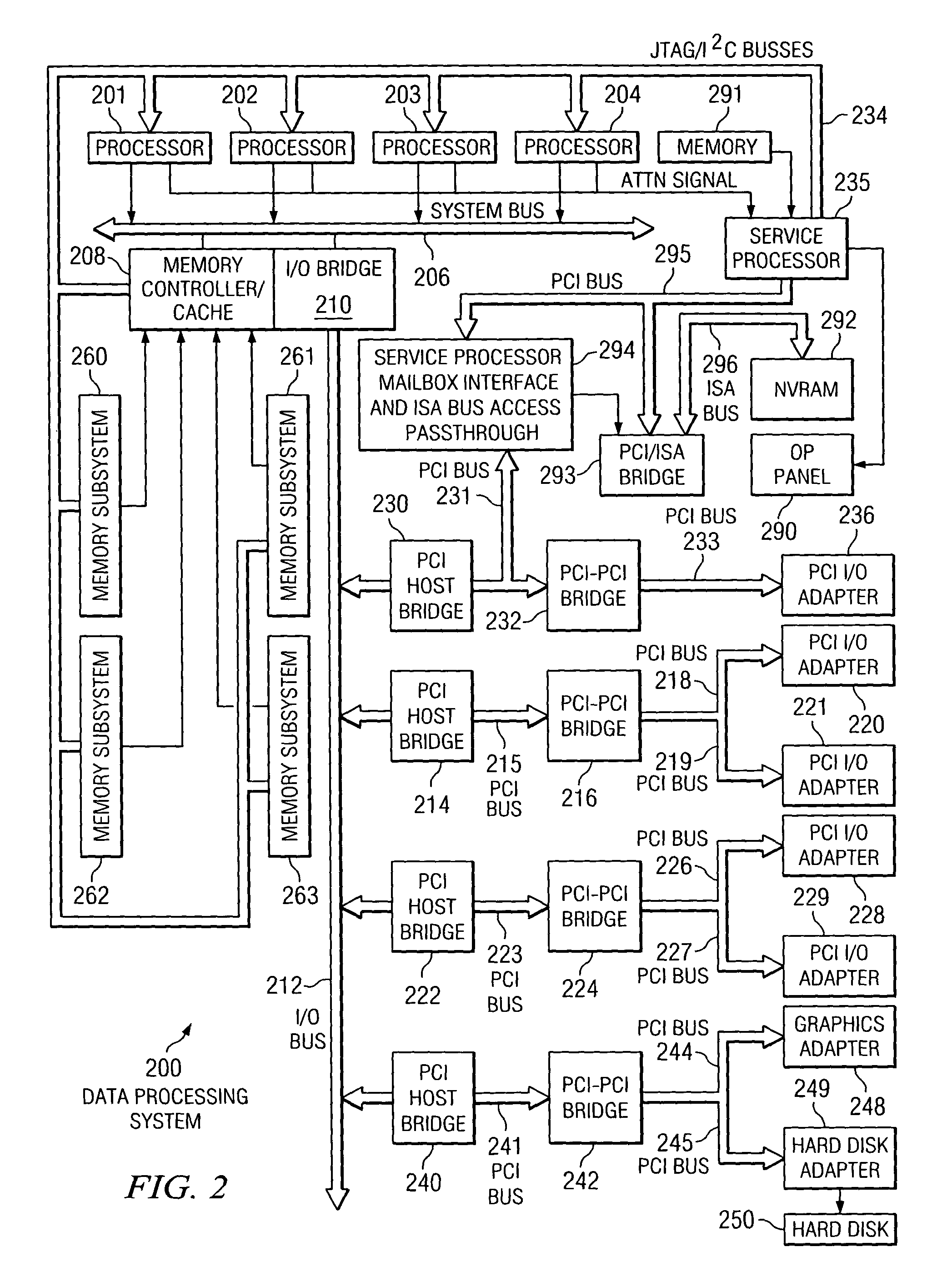
Currently, in a minimum system configuration with a single memory extent, there is no reliable method in computer memory fault isolation techniques to isolate a hardware problem among a memory module, such as a dual inline memory module (DIMM), a memory controller, and a memory card, which is the device to which memory modules are attached.
However, all components of memory systems are tested as one single unit and cannot be tested individually.
In addition to that, in the minimum configuration, when only one of each memory system component, such as memory controller, memory card, and memory module is present, any detected error may reside in any one of the interconnected elements and cannot be isolated.
Further, in the case of the minimum configuration, the prior art method makes it difficult to identify exact which component is defective.
Further to that, the prior art method also does not elaborately test the memory card component of memory system and the logic around it.
As a result, in the case of a defective memory card component, the problem cannot be isolated to the defective memory component and may increase the number of field replacement units in order to correct the memory system errors.

Method used


Image

  • Method, system, and product for isolating memory system defects to a particular memory system component
  • Method, system, and product for isolating memory system defects to a particular memory system component
  • Method, system, and product for isolating memory system defects to a particular memory system component

Examples


Embodiment Construction

[0019]A preferred embodiment of the present invention and its advantages are better understood by referring to the figures, like numerals being used for like and corresponding parts of the accompanying figures.

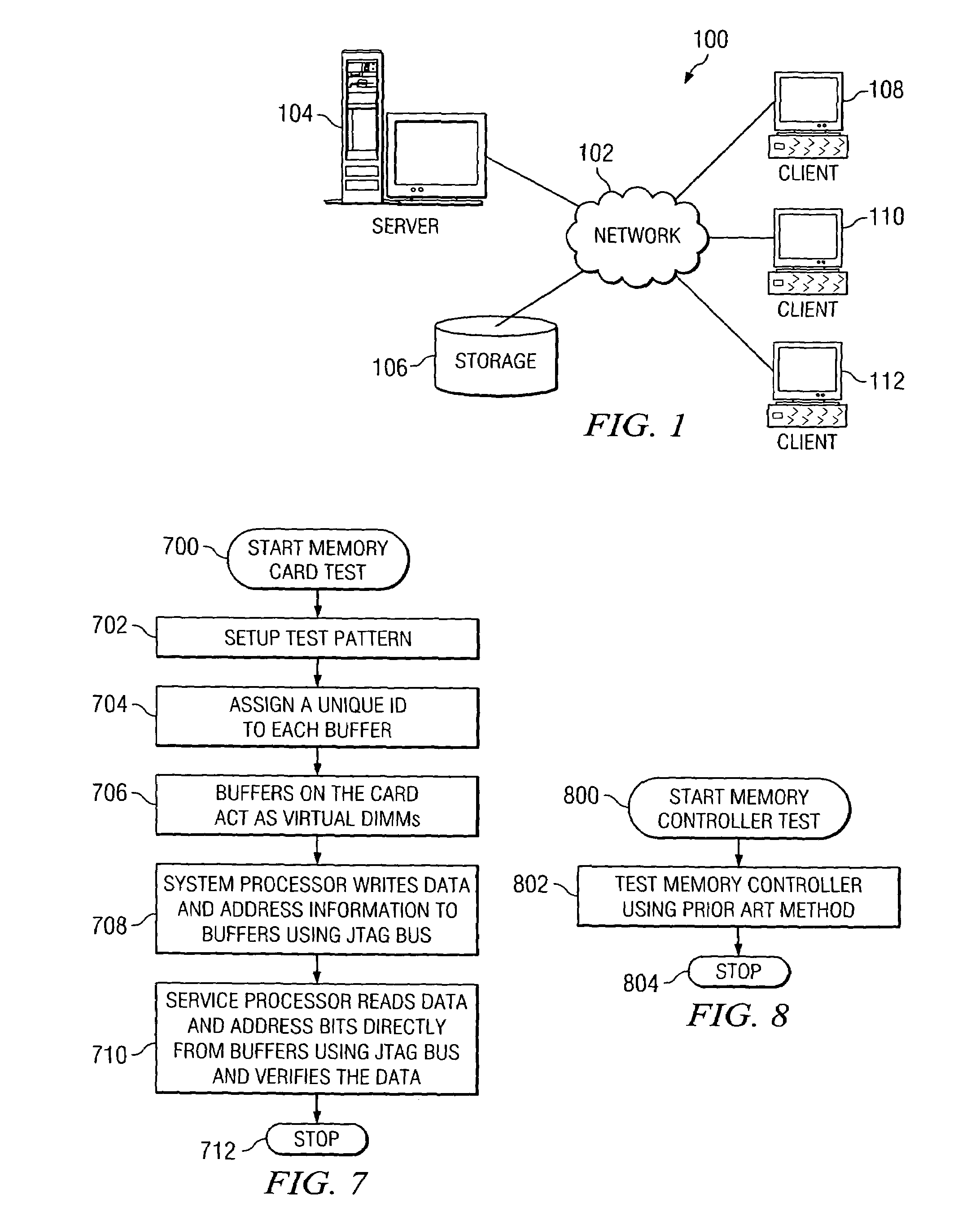
[0020]The present invention is a method, system, and computer program product for isolating a defect in a memory system by determining in which component of the memory system the defect exists, regardless of the system configuration, by testing each memory system component individually. The present invention reduces the number of field replacement units that must be carried by service persons by isolating a defect to a specific component of the memory system. In this manner, prior to calling a service person, the defective component is identified. Therefore, when a defect occurs, a call may be made to the service person, and the call may include an identification of the particular component of the memory system that is defective and that needs to be replaced. Thus, the defecti...


PUM


Abstract

A method, system, and product are disclosed for isolating a defect in a memory system by determining in which particular component of the memory system the defect exists. The memory system includes multiple components. The components include a physical memory module, a memory card to which the physical memory module is attached, and a memory controller for controlling the memory card. The memory card includes one or more electrical buffers for driving or detecting the memory signals. The buffers may be used as virtual memory elements. Each component is tested separately in order to identify the defective component with the help of virtual memory system elements. The components are tested by first testing the physical memory module. If the physical memory module passes the test, the memory card is then tested. If the memory card passes its test, the memory controller is tested.

Description

BACKGROUND OF THE INVENTION[0001]1. Technical Field[0002]The present invention relates generally to the field of data processing systems, and more specifically to a method, system, and computer program product for testing a memory system. Still more particularly, the present invention relates to a method, system, and computer program product for isolating a defect in a memory system by determining in which particular component of the memory system the defect exists.[0003]2. Description of Related Art[0004]Currently, in a minimum system configuration with a single memory extent, there is no reliable method in computer memory fault isolation techniques to isolate a hardware problem among a memory module, such as a dual inline memory module (DIMM), a memory controller, and a memory card, which is the device to which memory modules are attached. The known methods test all parts of the memory system coupled together. With all parts of the memory system coupled together, patterns of data ...

Claims


Application Information

Patent Timeline
Patent Type & Authority Patents(United States)
IPC IPC(8): G11C29/00G06F11/00G06F11/22H04L12/26
CPCG01R31/318533G01R31/318597G11C29/56008G11C2029/0409G11C5/04
Inventor GOODWIN, JOEL GERARDMISRA, MANISHUPTON, JOHN DANIEL
Owner INT BUSINESS MASCH CORP
Why Eureka
Try Eureka