
Method of operating an agricultural vehicle

a technology of agricultural vehicles and rotors, applied in the direction of threshers, instruments, threshers, etc., can solve the problems of operator injury, component rotation continues for a considerable time,

Active Publication Date: 2007-12-11
BLUE LEAF I P INC
View PDF4 Cites 0 Cited by
  • Summary
  • Abstract
  • Description
  • Claims
  • Application Information

AI Technical Summary

Benefits of technology

The present invention provides a method for reducing the time taken for agricultural vehicles to stop and start again, by reducing the engine speed and disengaging the drive from the rotating components when the vehicle is stopped. This allows the components to come to a standstill faster, reducing the time it takes to open the cover and access the machinery. An audible alarm signal is emitted while the components are still rotating to provide a visual indication of the speed of rotation and the time it will take for the machinery to stop. This method improves operational efficiency and reduces the operator's patience test.

Problems solved by technology

When operating an agricultural machine, such as a forage or combine harvester, one can sometimes pick up from the field an article that interferes with the operation of the machine or a blockage may occur within the machine for any of a variety of reasons.
Safety legislation in many countries requires an audible alarm to be sounded while it remains dangerous to remove the cover protecting the moving components.
The components are not normally braked and, as a result, after the operator disengages the drive from the vehicle engine, the components continue to rotate for a considerable time on account of their own inertia.
Waiting for the machinery to come to a complete standstill sometimes proves too frustrating for the operator and through impatience the cover is opened too soon, thereby creating a serious risk of injury to the operator.

Method used


Image

  • Method of operating an agricultural vehicle
  • Method of operating an agricultural vehicle

Examples


Embodiment Construction

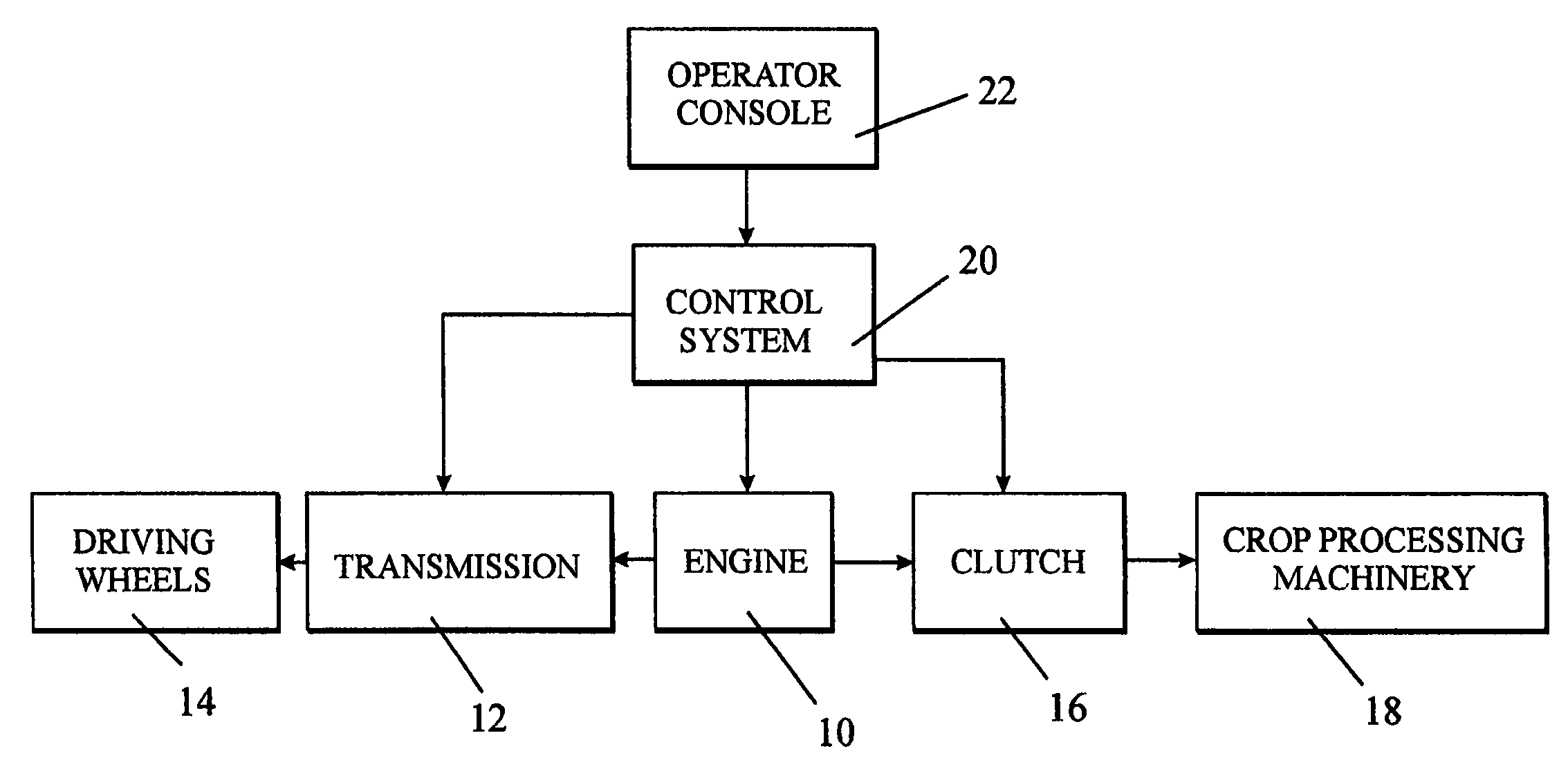
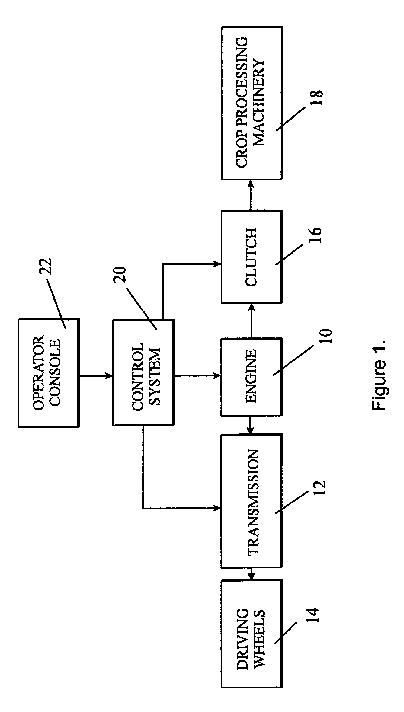
[0012]The single drawing is intended only to represent an agricultural machine for harvesting and / or processing crop, such as a conventional harvester and, though schematic, the diagram is believed to be sufficient for an understanding of the present invention. Reference may be made to numerous prior art patent specifications for a more detailed explanation of the operation of combine and forage harvesters, amongst them for example EP 1 387 230 and U.S. Pat. No. 6,690,285 both of which also address the problem of the risk of injury presented to the operator by rotating components of the crop processing machinery.

[0013]Referring to FIG. 1, the agricultural machine comprises an engine 10 which is connected to the driving wheels 14 through a variable ratio transmission 12. The same engine 10 drives crop processing machinery 18 through a clutch 16. The engine 10, the transmission 12 and the clutch 16 are controlled by a control system 20 which is itself connected to receive commands giv...


PUM


Abstract

A method is described for operating an agricultural vehicle to reduce the time taken for rotating components of the crop processing machinery driven by the vehicle engine to reach a standstill. The method comprises the steps of sensing when a signal is generated by the vehicle operator to disengage the drive from the engine to the rotating components, reducing the engine speed in response to the sensed signal to a minimum value below a steady idling speed of the engine, disengaging the drive to the rotating components after the engine speed has reached the minimum value, and increasing the engine speed to a value equal to or greater than the steady idling speed after the disengagement of the drive to the rotating components.

Description

FIELD OF THE INVENTION[0001]The present invention relates to a method of operating an agricultural vehicle to reduce the time taken for rotating components driven by the vehicle engine to reach a standstill.BACKGROUND OF THE INVENTION[0002]When operating an agricultural machine, such as a forage or combine harvester, one can sometimes pick up from the field an article that interferes with the operation of the machine or a blockage may occur within the machine for any of a variety of reasons. In such an event, the moving components involved in harvesting and processing the crop, need to be stopped so that the obstruction can be located and the problem remedied.[0003]The moving components are usually accessed by removing a cover and for safety reasons it is important that the cover should not be removed until all the moving components have come to a standstill. Safety legislation in many countries requires an audible alarm to be sounded while it remains dangerous to remove the cover p...

Claims


Application Information

Patent Timeline
Patent Type & Authority Patents(United States)
IPC IPC(8): A01D41/127A01D75/20B60W10/06B60W30/18
CPCA01D41/1274A01D75/20B60W10/06B60W30/1886Y10T477/6433B60Y2200/222Y10S56/02Y10T477/6418B60Y2200/22
Inventor AMEYE, DANNY R.BYTTEBIER, WARD M. R.
Owner BLUE LEAF I P INC
Learn More