Twin-clutch transmission

a transmission and twin-clutch technology, applied in mechanical equipment, transportation and packaging, gearwheels, etc., can solve the problem that the number of gearwheels cannot be reduced, and achieve the effect of reducing the number of gearwheels, reducing the size and weight, and shortening the center distan

Active Publication Date: 2007-12-11
HONDA MOTOR CO LTD
View PDF13 Cites 27 Cited by
  • Summary
  • Abstract
  • Description
  • Claims
  • Application Information

AI Technical Summary

Benefits of technology

[0014]The present invention has been made in view of the foregoing and it is one object of the invention to provide a twin-clutch transmission capable of being reduced in size and weight by shortening the center distance between input shafts and an auxiliary speed-change shaft or by reducing the number of gearwheels.
[0017]Thus, it is not necessary to provide a second gear pair on a second input shaft, so that a center distance is not increased.
[0018]In addition, the present invention provides a twin-clutch transmission including a first input shaft and a second input shaft connected, through a first clutch and a second clutch, respectively, to an input element, and disposed on the same axis. An auxiliary speed-change shaft is disposed parallel to the first and second input shafts with a plurality of gear pairs provided between the first and second input shafts and the auxiliary speed-change shaft. One of the first and second clutches is selectively engaged while the other is disengaged, and one of the first and second input shafts that is coupled to the corresponding one of the first and second clutches is interlocked with the auxiliary speed-change shaft through engagement of a required one of the plurality of gear pairs, thereby achieving a required speed-change ratio. A third clutch means is provided between the first input shaft and the second input shaft so that engagement and disengagement of the third clutch means may make it possible and impossible, respectively, to transmit power between the first input shaft and the second input shaft.
[0019]Since the clutch means is provided between the first input shaft and the second input shaft, one and the same gear pair can selectively transmits the rotation of the first input shaft and that of the second input shaft. It can be used for two speed-change gearing. Thus, the number of gears can be reduced, thereby providing the small-sized and lightweight transmission.

Problems solved by technology

In addition, since a gear pair cannot be used for another speed, the number of gearwheels cannot be reduced.

Method used


Image

  • Twin-clutch transmission
  • Twin-clutch transmission
  • Twin-clutch transmission

Examples


Embodiment Construction

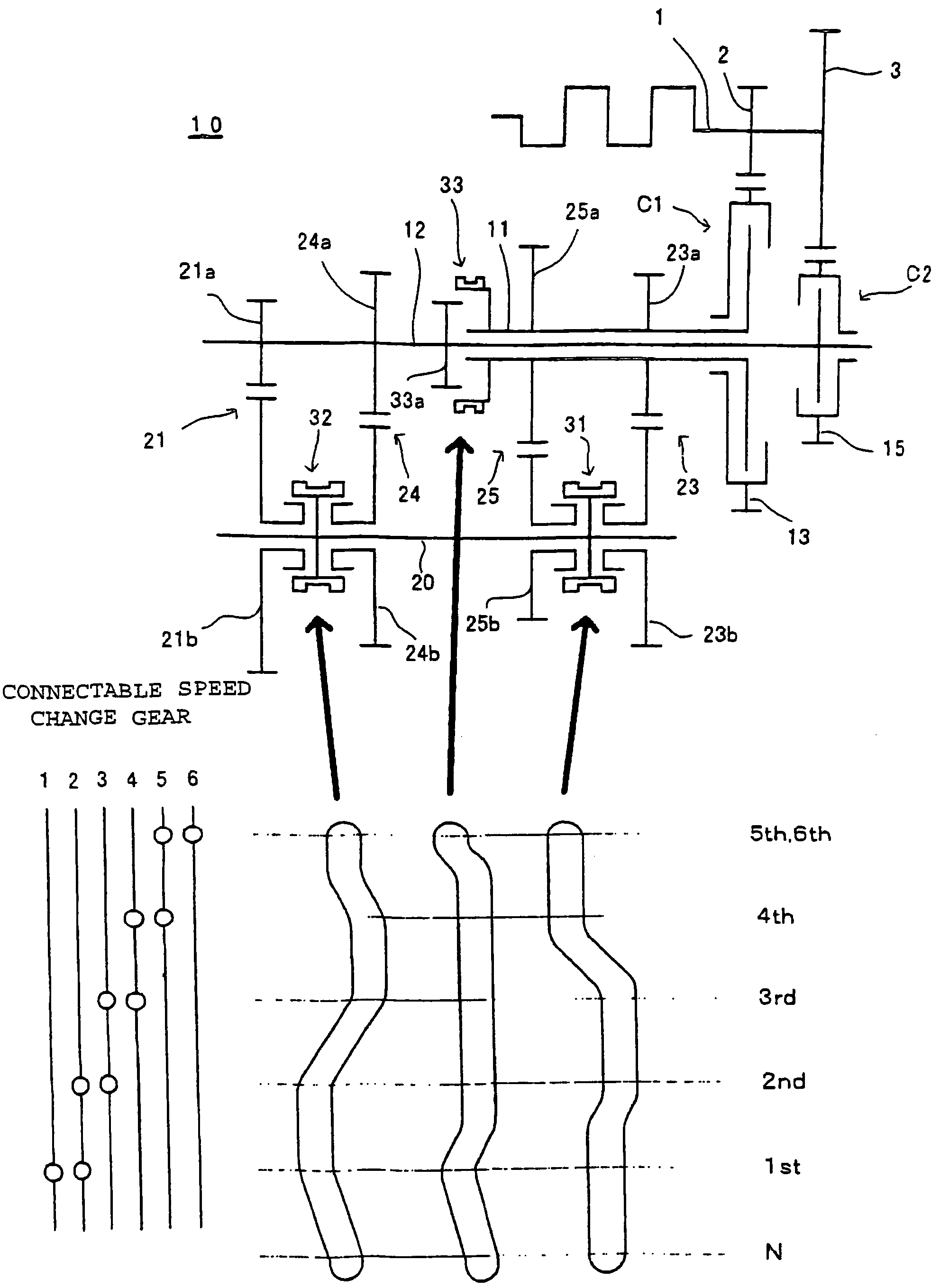
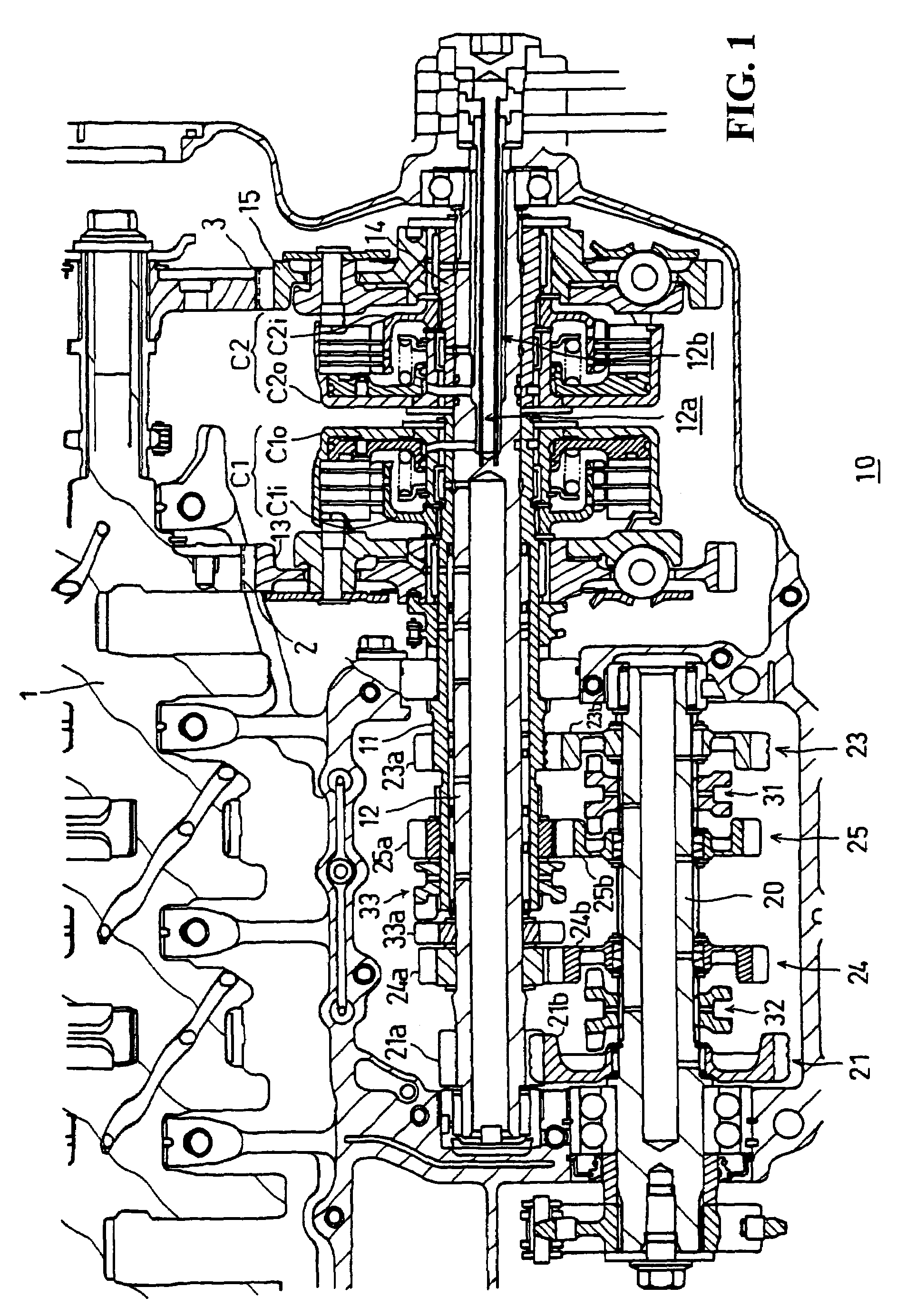
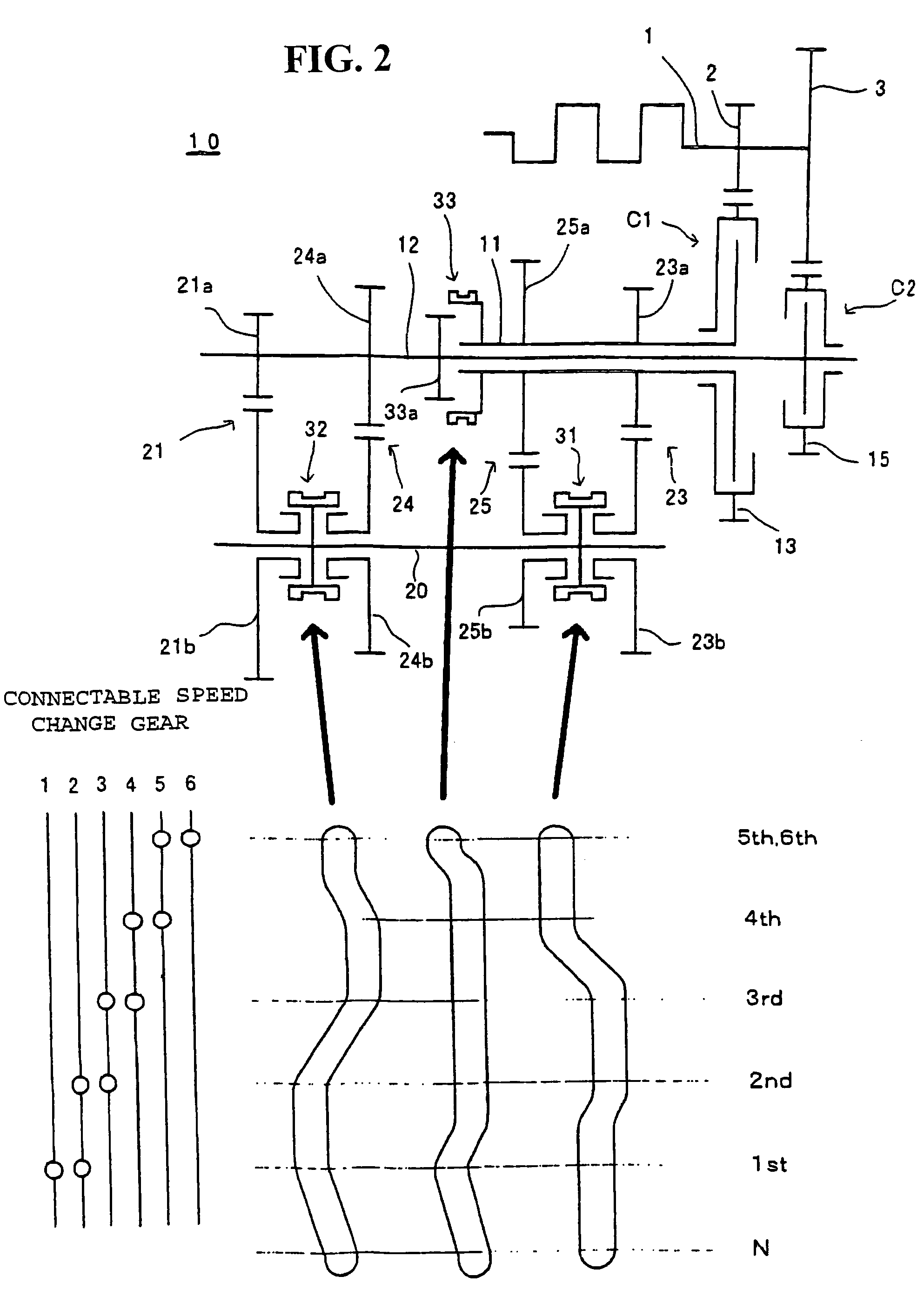
[0030]A preferred embodiment of the present invention is described below with reference to FIGS. 1 to 8.

[0031]A twin-clutch transmission 10 of the embodiment is configured such that a first input shaft 11 and a second input shaft 12 are coaxially nested with respected to one another and a crankshaft 1 and an auxiliary speed-change shaft 20 are disposed parallel to the first and second input shafts 11 and 12.

[0032]Referring to FIG. 1, the first input shaft 11 is partially carried on the outer surface of the second input shaft 12 in such a manner that both the input shafts are rotatable with respect to each other. A first clutch C1 is provided at the right end of the first input shaft 11 while a second clutch C2 is provided at a portion of the second input shaft 12 spaced to the right from the first input shaft 11. The first and second clutches C1 and C2 are disposed parallel to each other.

[0033]The clutch inner C1i of the first clutch C1 is integrally spline-fitted to the first input...


PUM


Abstract

A twin-clutch transmission wherein a center distance between input shafts and an auxiliary speed-change shaft can be shortened and the number of gears can be reduced. A twin-clutch transmission is provided which includes a first input shaft and a second input shaft, an auxiliary speed-change shaft, and a plurality of gear pairs. The first and second input shaft are connected, through a first clutch and a second clutch, respectively, to an input element, and disposed on the same axis. The auxiliary speed-change shaft is disposed parallel to the first and second input shafts. The plurality of gear pairs are provided between the first and second input shafts and the auxiliary speed-change shaft. An input path from the input element to the first clutch is different from that to the second clutch, and primary ratios of the input paths are set to values, respectively, different from each other.

Description

BACKGROUND OF THE INVENTIONCROSS-REFERENCE TO RELATED APPLICATIONS[0001]The present application claims priority under 35 USC 119 to Japanese Patent Application No. 2004-090163 filed on Mar. 25, 2004 the entire contents of which are hereby incorporated by reference.[0002]1. Field of the Invention[0003]The present invention relates generally to a twin-clutch transmission having two clutches that are selectively used to direct power from an input element to the transmission.[0004]2. Description of Background Art[0005]Various types of such twin-clutch transmissions have been proposed, as disclosed in U.S. Pat. No. 5,890,392.[0006]In the twin-clutch transmission disclosed in U.S. Pat. No. 5,890,392, two clutches that are provided as input parts have a common clutch cage to which rotation of a crankshaft is transmitted. Two input shafts are concentrically connected to the common clutch cage via respective friction plates. One of the two input shafts surrounds the other.[0007]Six gear pair...

Claims


Application Information

Patent Timeline
Patent Type & Authority Patents(United States)
IPC IPC(8): F16H3/38F16H3/08F16H3/083B60K17/08F16H3/00F16H3/089F16H3/093
CPCF16H3/006F16H61/688F16H3/093F16H63/18Y10T74/19288F16H2063/025Y10T74/19223Y10T74/19228F16H2003/0933
Inventor SUZUKI, OSAMUTOMODA, AKIHIKO
Owner HONDA MOTOR CO LTD
Why Eureka
Try Eureka