Ball valve with snap-in stem

a ball valve and stem technology, applied in the field of quarter-turn ball valves, can solve the problems of more complicated manufacturing structures, and achieve the effect of facilitating the snap-in stem

Inactive Publication Date: 2007-12-11
NIBCO INC
View PDF27 Cites 40 Cited by
  • Summary
  • Abstract
  • Description
  • Claims
  • Application Information

AI Technical Summary

Benefits of technology

[0003]The ball valve of the present invention satisfies this need by providing a ball valve having a ball with resilient, opposed facing spaced-apart locking arms which engage a stem having outwardly projecting flanges to allow the stem to be inserted externally into the valve body and snap-locked to the resilient opposed locking arms of the ball. In a preferred embodiment also, the edges of the arms facing the stem-receiving aperture and the flanges of the stem are tapered to facilitate the snap insertion of the stem to the ball. In a preferred embodiment, the stem includes a locking groove into which the tips of the locking arms fit once the stem is snap-locked to the ball. Thus, the stem can be readily coupled to the ball externally through the stem opening.

Problems solved by technology

Both of these types of systems are either somewhat difficult to assemble and / or result in more complicated structures for manufacturing.

Method used


Image

  • Ball valve with snap-in stem
  • Ball valve with snap-in stem
  • Ball valve with snap-in stem

Examples


Embodiment Construction

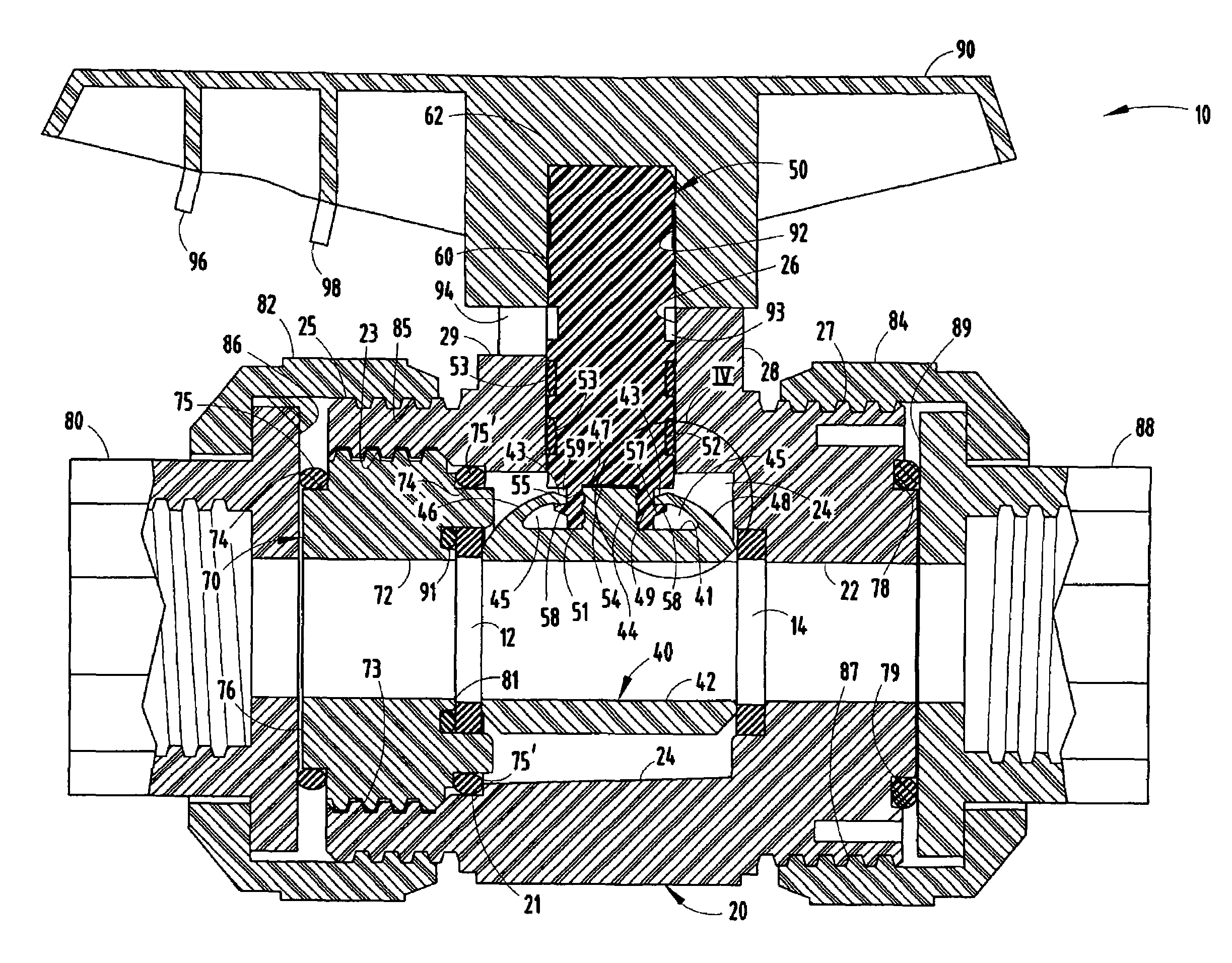
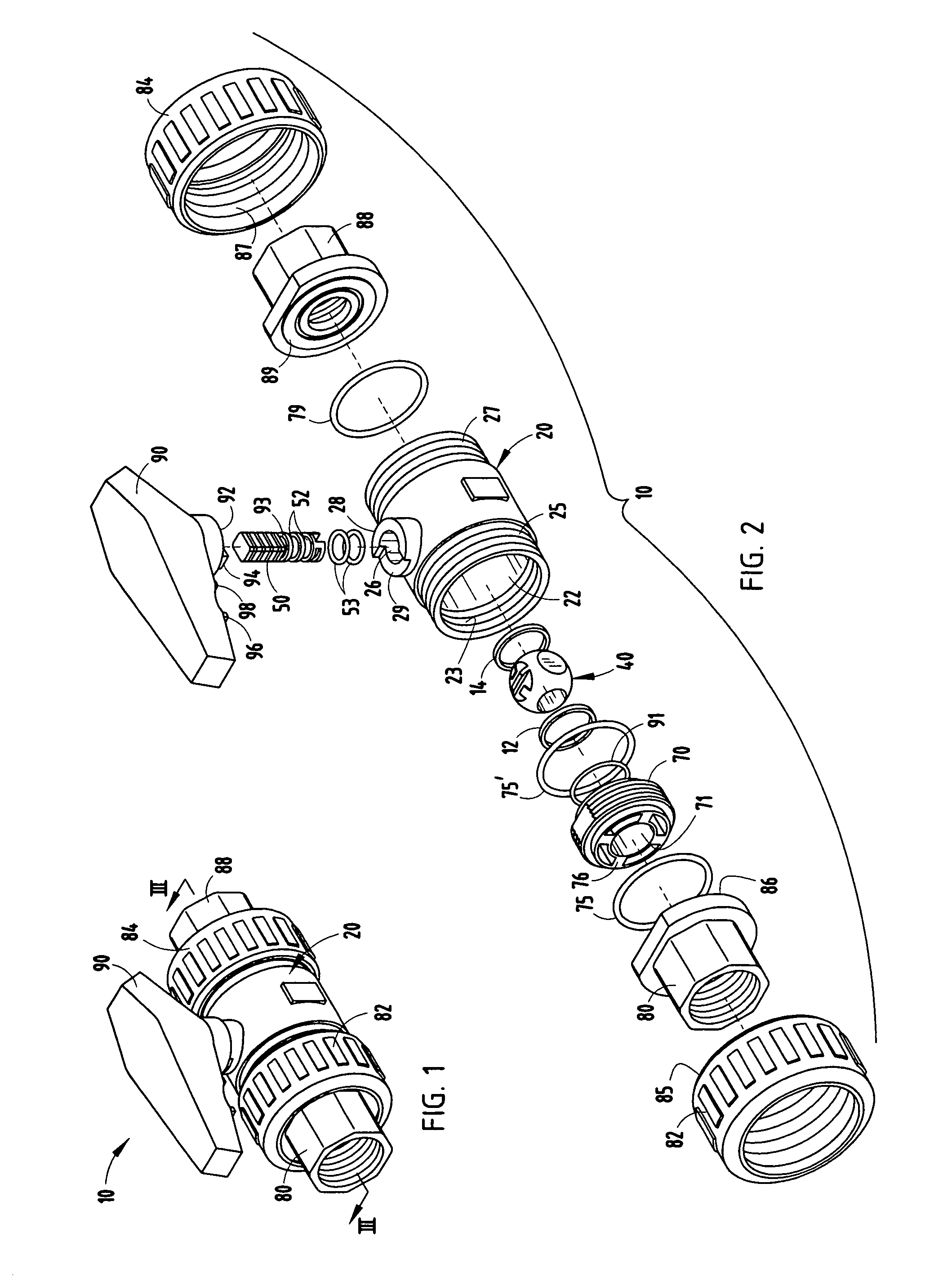
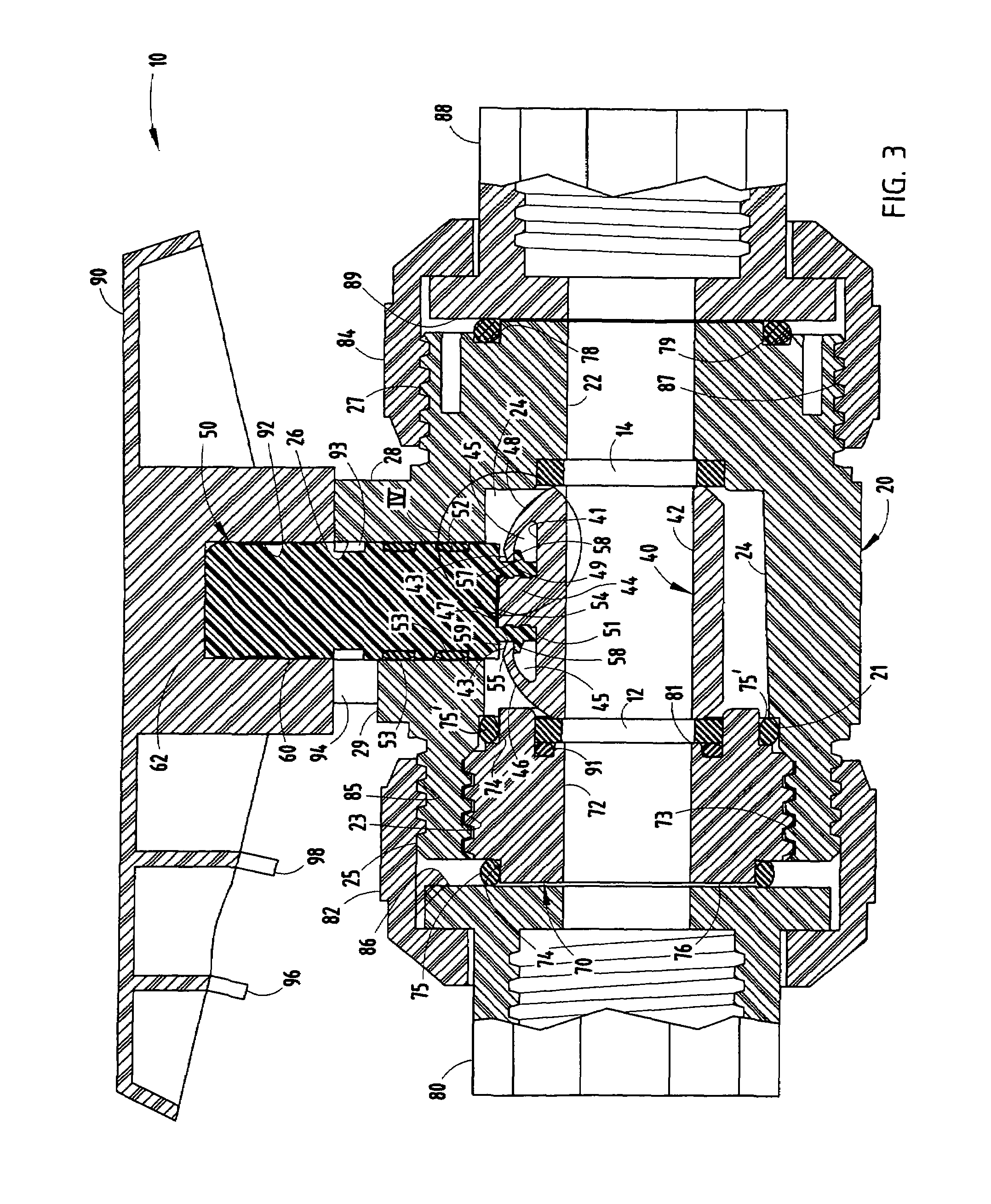
[0017]Referring initially to FIGS. 1-3, there is shown a valve 10 embodying the present invention. The valve includes a valve body 20 having a central axially extending bore 22 providing a fluid flow path through the valve body, a central ball-receiving chamber 24 (as best seen in FIG. 3), and a stem-receiving bore 26 communicating with chamber 24. Chamber 24 is internally threaded at end 23 for receiving a threaded retainer carrier 70, which also includes a cylindrical axially extending bore 71 aligned with valve bore 22. Body 20 includes a quarter-turn limiting handle mounting boss 28 which includes an arcuate slot 29 formed therein which cooperates with a projecting tab 94 on handle 90 for limiting the range of motion of the ball valve to 90° or a quarter turn in a controlled manner. Valve body 20 has opposed ends 25 and 27 which are externally threaded for receiving union nuts as described below.

[0018]The ball chamber 24 receives a pair of ball seat seals 12 and 14, as seen in F...


PUM


Abstract

A ball valve has a ball with resilient, opposed facing spaced-apart locking arms which engage a stem having outwardly projecting flanges to allow the stem to be inserted externally into the valve body and snap-locked to the resilient opposed locking arms of the ball. In one embodiment, the stem includes a breakaway groove to prevent over torquing of the stem. In another embodiment, a retainer carrier for the ball includes slots for receiving integrally formed projection tabs on the underside of the valve handle which are spaced and sized to interfit with the slots of the threaded retainer carrier such that, if ball or seal replacement becomes necessary, the valve handle itself can serve as a removal tool for the retainer carrier.

Description

BACKGROUND OF THE INVENTION[0001]The present invention relates to quarter-turn ball valves with an improved coupling between the ball and stem.[0002]Typical ball valves have a housing which includes an axially extending fluid communication path and a ball receiving chamber into which a ball element of the valve is inserted. The valve body also includes an opening extending orthogonally to the flow path for receiving a stem which typically includes a locking flange, such that the stem can be inserted through the stem aperture from the ball valve chamber and the ball subsequently loaded into the chamber with interlocking tongue and groove members for coupling the stem and ball. Some ball valve proposals allow the stem to be inserted from the outside of the valve body. Such construction requires a locking flange within the valve body and / or a retainer on the stem to retain the stem in locked position with respect to the valve body. Both of these types of systems are either somewhat dif...

Claims


Application Information

Patent Timeline
Patent Type & Authority Patents(United States)
IPC IPC(8): F16K17/14
CPCF16K5/0626F16K27/067F16K5/0647Y10T137/6109Y10T137/0508Y10T137/8811Y10T137/6035
Inventor GRUENER, SR., ROBERT B.
Owner NIBCO INC
Why Eureka
Try Eureka