
Bonding apparatus

a technology of suspension and bonding apparatus, which is applied in the direction of soldering apparatus, manufacturing tools,auxillary welding devices, etc., can solve the problem of inability to perform stable bonding, and achieve the effect of high-stable bonding

Inactive Publication Date: 2007-12-11
SHINKAWA CO LTD
View PDF7 Cites 7 Cited by
  • Summary
  • Abstract
  • Description
  • Claims
  • Application Information

AI Technical Summary

Benefits of technology

[0007]The object of the present invention is to provide a bonding apparatus that eliminates the inertial force of the bonding arm and the reaction force of the driving motor, thus making it possible to realize high-speed, highly stable bonding.

Problems solved by technology

There is another problem.
When the bonding arm is driven by the driving motor, the bonding arm as a whole vibrates by the reaction force of the motor, so that stable bonding cannot be performed.

Method used


Image

  • Bonding apparatus
  • Bonding apparatus
  • Bonding apparatus

Examples


Embodiment Construction

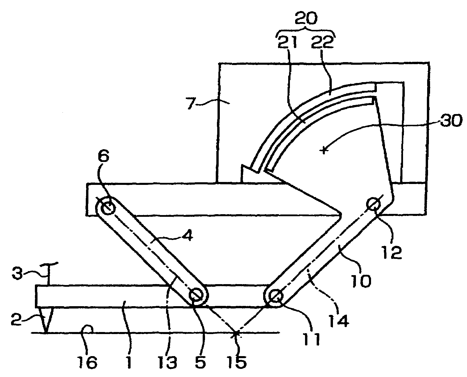
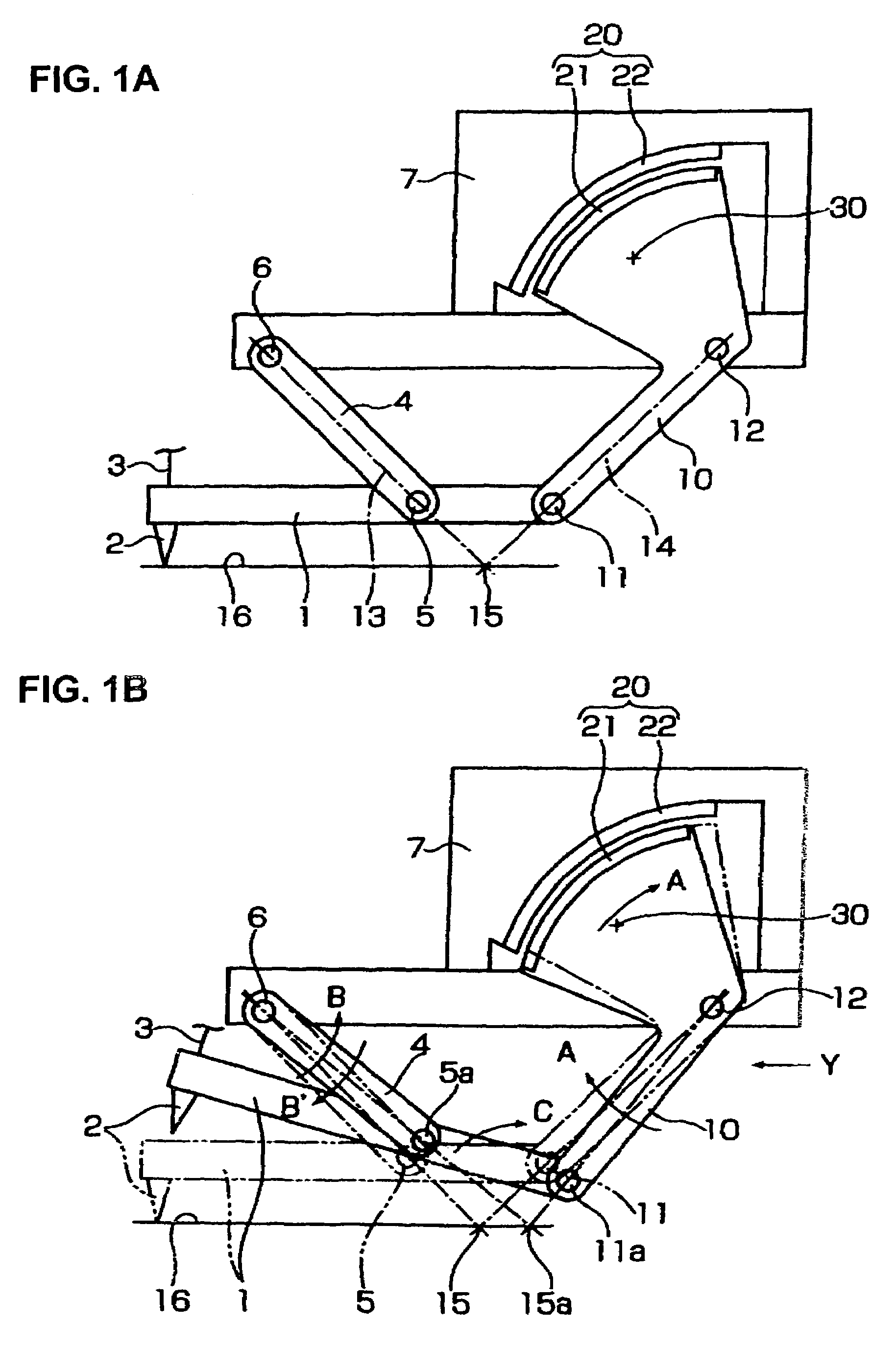
[0017]The basic operating principle of the overhead suspension type bonding apparatus according to the present invention will be described with reference to FIGS. 1A and 1B.

[0018]A capillary 2 is attached to the end portion of the bonding arm 1, and a wire 3 that is wound on a wire spool (not shown in the drawings) passes through the capillary 2.

[0019]A front link 4 is connected to the bonding arm 1 via a supporting shaft 5 so that the lower end portion of a this front link 4 is free to rotate, and the upper end portion of this front link 4 is connected to a bonding head 7 via a supporting shaft 6 so that the upper end portion is free to rotate. Although not shown, the upper surface of the bonding head 7 is fastened to an XY table that is driven in the directions of the X and Y axes, and the XY table is fastened to the overhead part of the bridge stand of the bonding apparatus.

[0020]A rear link 10 is connected to the rear end portion of the bonding arm 1 via a supporting shaft 11 so...


PUM

PropertyMeasurementUnit
gravityaaaaaaaaaa
inertial forcesaaaaaaaaaa
circular arc shapeaaaaaaaaaa

Abstract

A bonding apparatus including a front link whose lower end is rotatably connected to a bonding arm and upper portion is rotatably connected to bonding head, and a rear link whose lower end is rotatably connected to the rear end of the bonding arm and upper portion is rotatably connected to the bonding head; and a hypothetical rotational center of capillary of the bonding arm is on a bonding surface and set to be the intersection of a line that connects upper and lower rotational centers of the front link and a line that connects upper and lower rotational centers of the rear link, wherein the immovable element of motor is fastened to the bonding head, and the rotational element of the motor is attached to the upper end of the rear link so that the rotational element rotates about the upper rotational center of the rear link.

Description

BACKGROUND OF THE INVENTION[0001]1. Technical Field[0002]The present invention relates to an overhead suspension type bonding apparatus in which the bonding head is suspended from an overhead part.[0003]2. Description of the Related Art[0004]An overhead suspension type bonding apparatus has several characterizing features. Namely, since the bonding head is suspended from an overhead part, a workpiece that has a wide bonding area can be bonded. For instance, Japanese Patent Application Laid-Open (Kokai) Nos. 2001-168135 and 2003-297872 disclose bonding apparatuses of this type.[0005]The bonding apparatus of the above-described prior art type has a structure that includes: a bonding arm which has a capillary, a front arm on which the bonding arm is supported by a supporting shaft so that the bonding arm is rotatable and whose upper portion is attached to a bonding head so that the front arm is swingable, a back arm whose front side is supported on the bonding head so that the back arm...

Claims


Application Information

Patent Timeline
Patent Type & Authority Patents(United States)
IPC IPC(8): H01L21/60B23K1/06B23K20/00
CPCB23K20/005H01L2224/78823H01L2224/7835H01L2224/78301
Inventor KAKUTANI, OSAMUKONDO, YUTAKASEINO, YOSHIHIKO
Owner SHINKAWA CO LTD
Learn More