Endoscopic instruments

a technology of endoscopic instruments and sutures, applied in the field of sutures, can solve the problems of high surgical operation cost, post-operative hospitalization, and high surgical invasiveness, and achieve the effect of accurately suturing in-vivo tissu

Inactive Publication Date: 2007-12-11
OLYMPUS CORP
View PDF36 Cites 40 Cited by
  • Summary
  • Abstract
  • Description
  • Claims
  • Application Information

AI Technical Summary

Benefits of technology

[0015]The first objective of the present invention is to provide a suture instrument that can accurately suture in-vivo tissue.

Problems solved by technology

A surgical operation, however, is highly invasive because it naturally requires an incision to the patient body.
Furthermore, it requires post-operative hospitalization, the cost of which can be a heavy burden for the patient.
However, in the arrangement disclosed in U.S. Pat. No. 5,792,153, fine control of location of the penetration is very difficult because penetration is performed with the tissue placed inside the cavity.
This will prevent the tissue from being securely sutured, or will require more stitches than necessary, resulting in extended operation time.
Moreover, inability to control the intervals between the stitches will prevent the tissue from being securely sutured with less number of stitches.
These two operations, required per penetration, will make the treatment procedure very complicated, extending the treatment time as well.
Application of the procedure will be limited because the size of the cavity determines the area to penetrate at one time, making suture impossible when the suture area is too large to suck in the cavity.
If the length or the height of the cavity is increased to hold more tissue to be sutured, there will inevitably be an increase in length and diameter of the instrument (a) itself, making it impossible to insert it into the body lumen or to locate the penetration for accurate suture.
These can not only impose more burdens onto the patient at the time of its insertion but also possibly extend the treatment time.
This can accidentally cause the operator to prick his finger with the needle while he is trying to insert the tag into it.

Method used


Image

  • Endoscopic instruments
  • Endoscopic instruments
  • Endoscopic instruments

Examples


first embodiment (

FIGS. 1 to 18)

[0046]Description of a Piercing Device and a Knot Pusher (FIGS. 1 to 9)

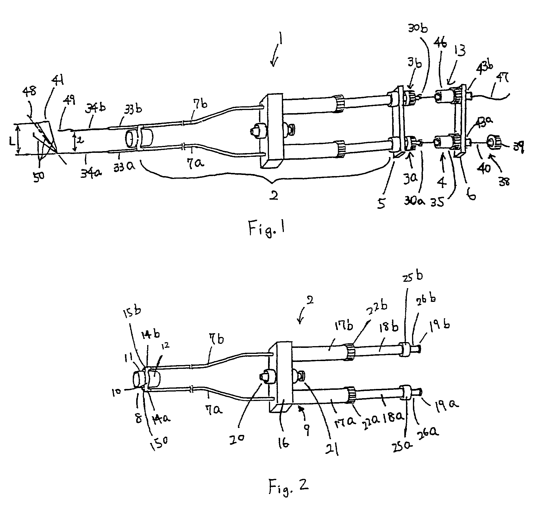
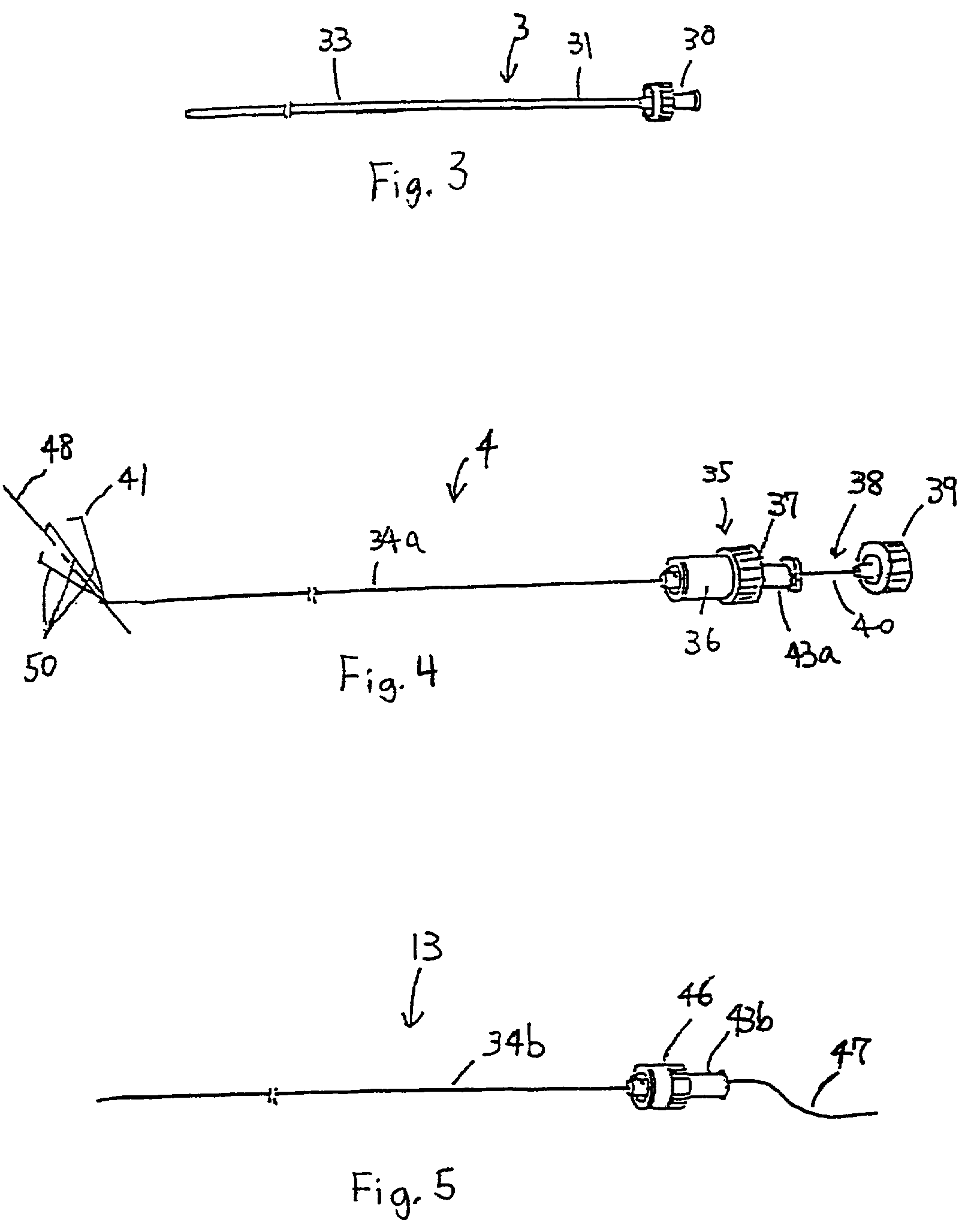
[0047]A piercing device 1 comprises a main body 2, inner sheaths 3a and 3b, needles 4 and 13, an inner sheaths-coupling member 5, and a needles-coupling member 6.

[0048]The main body 2 comprises two outer sheaths 7a and 7b, caps 8 connected at the distal ends of the sheaths 7a and 7b, and an operation section 9 connected at the proximal end of the sheaths 7a and 7b. The cap 8 comprises an outer sheaths-connecting section 10, a distal cylindrical section 11, and a distal mounting section 12. The distal cylindrical section 11 is made of a relatively hard material. Preferably, it is made of a transparent plastic material such as polycarbonate lest it should obstruct the vision of a first endoscope 27. Preferably, the inner diameter is about 5 to 15 mm, the wall thickness is about 1 mm. The length is about 3 to 10 mm, and a shorter cylinder is better.

[0049]The distal mounting section 12 is cylindrical an...

second embodiment (

FIGS. 19 to 21)

[0110]Only points different from those of the first embodiment are described.

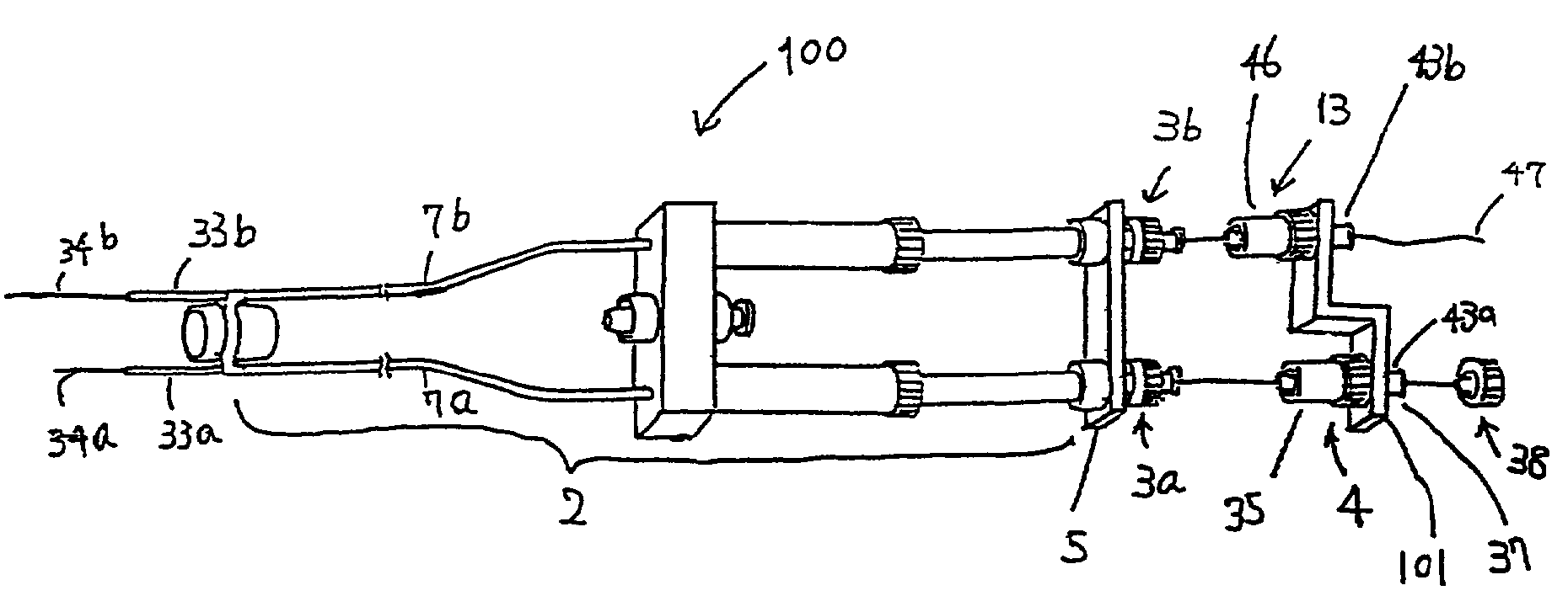
[0111]A piercing device 100 is the piercing device 1 with the needles-coupling member 6 replaced by a needles-coupling member 101. The needles-coupling member 101 comprising a distal section 102, a middle section 103 and a proximal section 104, and is shaped like a crank. The distal section 102 and the proximal section 104 are positioned longitudinally apart each other. The distal section 102 should be apart from the proximal section 104 by at least the thickness of tissue to be penetrated, or at least 5 mm.

[0112]Coupling holes 45a and 45b of the needles-coupling member 101 are mounted via the slits 44a and 44b to the narrow sections 43a and 43b of the needle port 37 and needle grip 46. Because the distal section 102 and the proximal section 104 are apart each other, the distal ends of the needle bodies 34a and 34b are longitudinally apart from each other. When the needles-coupling member 101...


PUM


Abstract

A tissue-piercing device includes two piercing members, and an operation section to which a proximal end of each of the piercing members is connected. Each of the piercing members includes a flexible outer sheath, a slidable inner sheath which is slidably inserted in the outer sheath, and a slidable needle which is inserted in the inner sheath. A switch portion is provided for switching between an operation mode in which a piercing action by the two piercing members is performed in a single operation, and an operation mode in which piercing actions by the two piercing members are performed in respective separate operations. The switch portion includes a sheath-coupling member to couple and decouple the two slidable inner sheaths. The switch portion may include a needle-coupling member to couple and decouple the two slidable needles.

Description

CROSS-REFERENCE TO RELATED APPLICATION[0001]This application claims the benefit of U.S. Provisional Application to Koichi Kawashima et al, entitled “Endoscopic Instruments,” application No. 60 / 281,015, filed Apr. 4, 2001.BACKGROUND OF THE INVENTION[0002]1. Field of the Invention[0003]The present invention relates to suture instruments that are used for endoscopically suturing tissue in the living body, especially to those suture instruments used in conjunction with flexible endoscopes.[0004]2. Description of the Related Art[0005]Currently, in many cases, in-vivo tissue of a patient is sutured through surgical operation. A surgical operation, however, is highly invasive because it naturally requires an incision to the patient body. Furthermore, it requires post-operative hospitalization, the cost of which can be a heavy burden for the patient. In these circumstances, the development of a low-invasive oral endoscopic procedure that eliminates the need for open surgery is anticipated.[...

Claims


Application Information

Patent Timeline
Patent Type & Authority Patents(United States)
IPC IPC(8): A61B17/04A61B17/00A61B17/06A61B17/12A61B17/125A61B17/34
CPCA61B17/0469A61B17/06109A61B2017/061A61B2017/0472A61B2017/0474A61B2017/003
Inventor KAWASHIMA, KOICHISUZUKI, TAKAYUKIONUKI, YOSHIO
Owner OLYMPUS CORP
Why Eureka
Try Eureka