
Arrangement used to fix conductor rails for multi-phase switchgears

a multi-phase switchgear and fixing technology, applied in the direction of electromagnetic relay details, contact, coupling device connection, etc., can solve the problems of increasing importance, achieve the effect of improving the tolerance of the distance between the receiving hole, improving the tolerance of tensile and compressive forces, and improving handling

Active Publication Date: 2007-12-11
KLOCKNER-MOELLER GMBH
View PDF13 Cites 0 Cited by
  • Summary
  • Abstract
  • Description
  • Claims
  • Application Information

AI Technical Summary

Benefits of technology

"The present invention provides an arrangement for securing contact straps for multiphase switching devices. The arrangement includes straight guide elements for receiving contact straps, through-holes in the contact straps, and insertion pins that secure the contact straps in position. The contact straps are easy to mount and remove, and the process of securing them can be automated. The arrangement eliminates the need for female threads and threaded plates, reducing the impact of magnetic interference. The insertion comb is easy to manipulate, and recycling is possible. The design of the insertion pins and the connecting web compensates for tolerances and allows for improved handling. The contact straps can be secured with knobs, and the phase barriers of the switching device housing support the inserted insertion comb. The arrangement also includes compensating slots in the connecting web and receiving slots in the phase barriers, which increase the permissible tensile and compressive forces on the connecting terminals."

Problems solved by technology

This problem is increasing in importance due to the trend toward switching devices of smaller and smaller size.

Method used


Image

  • Arrangement used to fix conductor rails for multi-phase switchgears
  • Arrangement used to fix conductor rails for multi-phase switchgears
  • Arrangement used to fix conductor rails for multi-phase switchgears

Examples


Embodiment Construction

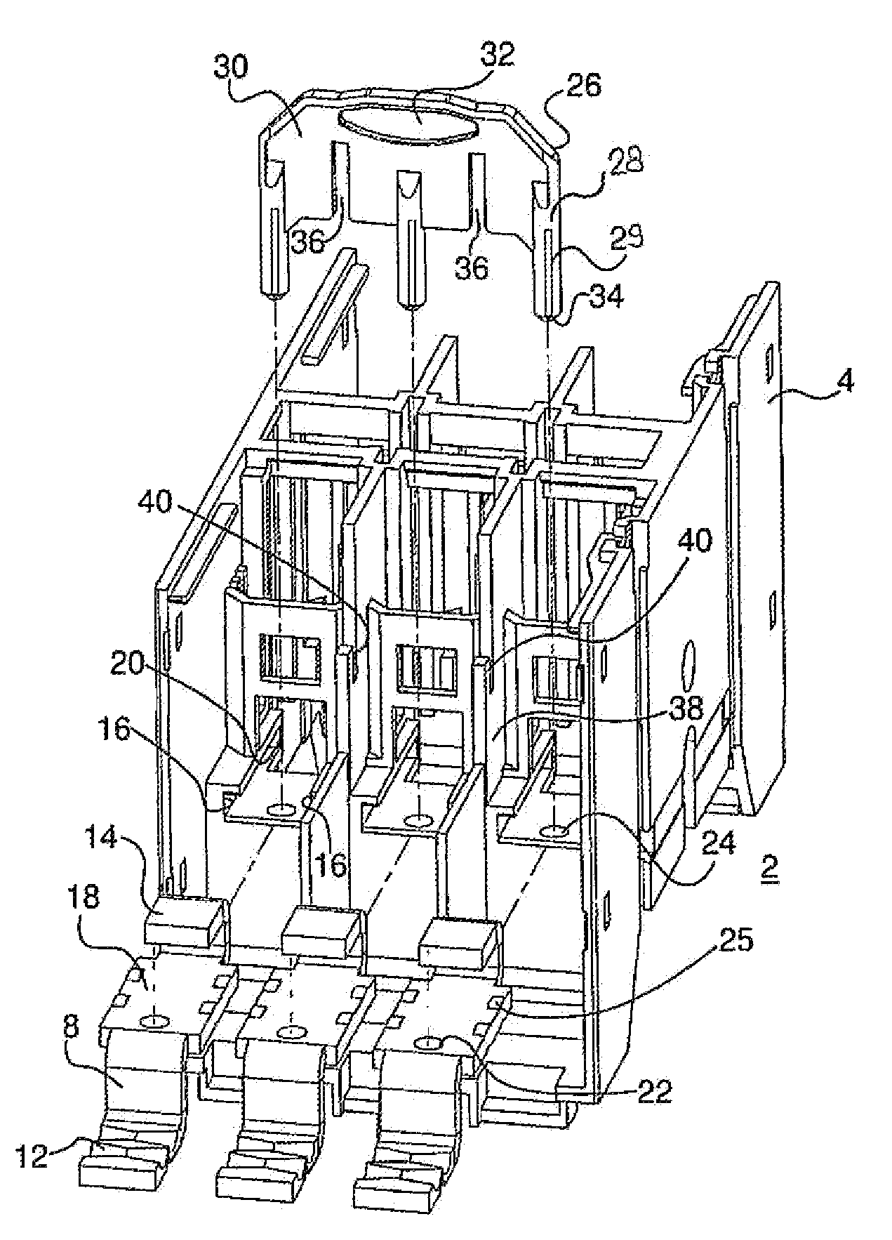
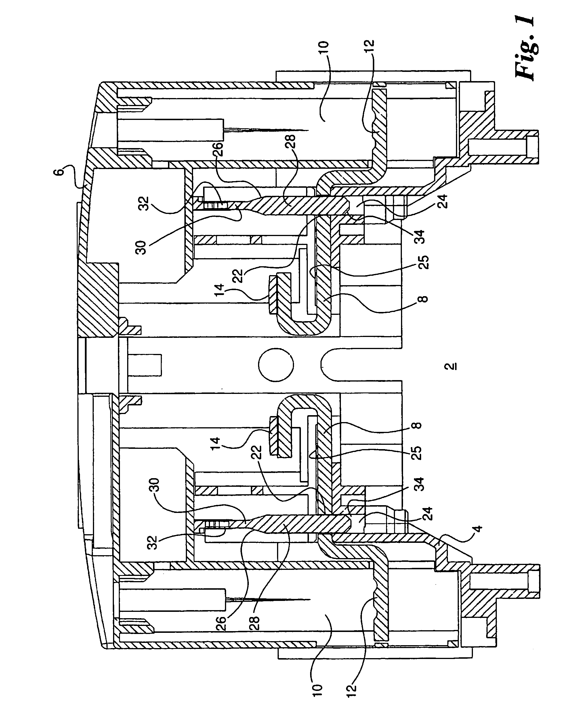
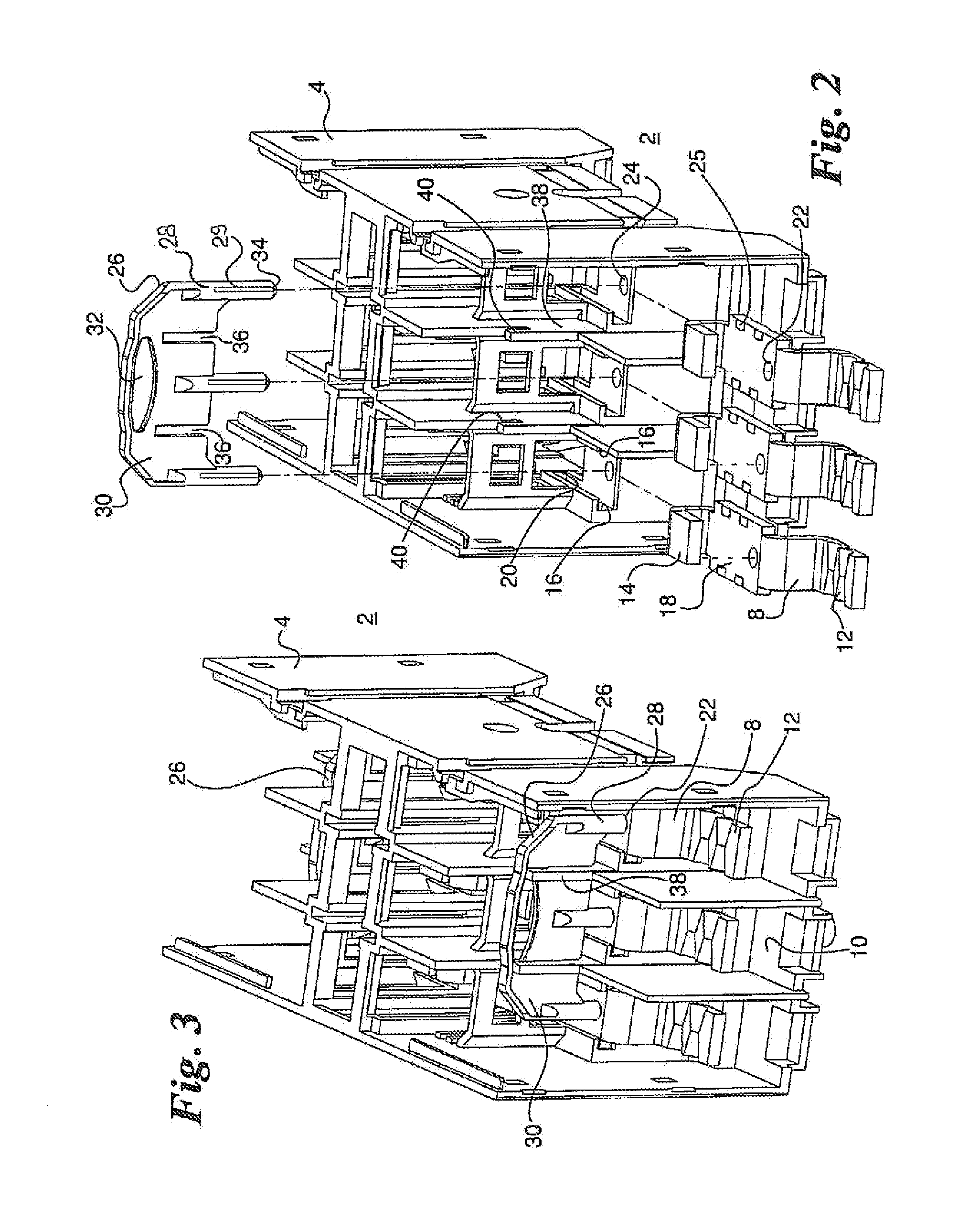
[0016]The drawing shows the arrangement for securing contact straps, including the parts of a multi-pole switching device 2 in the form of a three-pole contactor that are useful to illustrate one embodiment of the invention. Switching device 2 is surrounded by a switching device housing 4, of which only the upper housing part is depicted in the drawing. Switching device housing 4 is closed at the front by a removable housing cover 6, as shown in FIG. 1. For each current phase, one incoming and one outgoing contact strap 8 is secured in switching device housing 4. Each contact strap 8 is provided at its outer end with a connecting terminal 12 extending into the respective terminal compartment 10, and has a stationary contact member 14 at its inner end. The contact straps 8 belonging to a phase are electrically connected and disconnected by a contact bridge in a usual manner; stationary contact members 14 being brought into and out of contact with movable contact members attached to t...


PUM


Abstract

An arrangement used to fix conductor rails for multi-phase switchgears to allow for mounting and dismantling the conductor rails in a simple manner is provided. The switchgear housing (4) comprises straight guide elements (16) which are used to receive the mounting position using the conductor rails (8). Each conductor rail (8) includes a continuous bore (22) which is covered by a receiving bore (24) when in a mounted position, the receiving bore being formed in the switchgear housing (4). Insertion journals (28) extend through the continuous bores (22) into the receiving bores (24) associated therewith and are combined with a connecting web (30) in order to form an insertion comb (26) made of an insulating material.

Description

[0001]The present invention relates to an arrangement for securing contact straps for multiphase switching devices, in particular for contactors, in which the incoming and outgoing contact straps secured in the switching device housing each have a connecting terminal at their outer end and lead to a stationary contact member with their inner end. The stationary contact member is brought into operative contact with a movable contact member.BACKGROUND[0002]Contact straps in multiphase electrical switching devices have a connecting terminal at their outer end and are directly or indirectly connected to a stationary contact member with their inner end, said stationary contact member being brought into and out of contact with a movable contact member. It is known for contact straps to be secured in the switching device housing by pressing them in or embedding them by an injection molding process (DE 19904355 A1), by adhesive bonding (DE 10036350 A1), by a screw connection with a female t...

Claims


Application Information

Patent Timeline
Patent Type & Authority Patents(United States)
IPC IPC(8): H01H13/04H01H11/06H01H50/54
CPCH01H50/546H01H11/06
Inventor GERVING, KARSTENKREMERS, WOLFGANG
Owner KLOCKNER-MOELLER GMBH
Learn More