

Techniques for using chirped fields to reconfigure a medium that stores spectral features
a technology of chirped fields and spectral features, applied in the field of reconfiguring a medium that stores spectral features, can solve the problems of requiring a long time, requiring a large amount of energy, and a large amount of waiting time, and achieve the effect of shortening the tim
- Summary
- Abstract
- Description
- Claims
- Application Information
AI Technical Summary
Benefits of technology
Problems solved by technology
Method used
Image

Examples
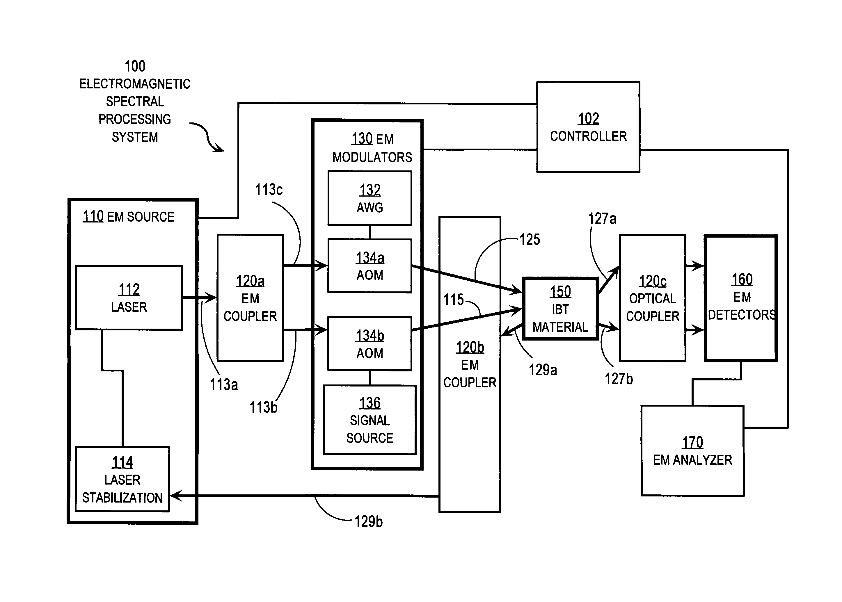
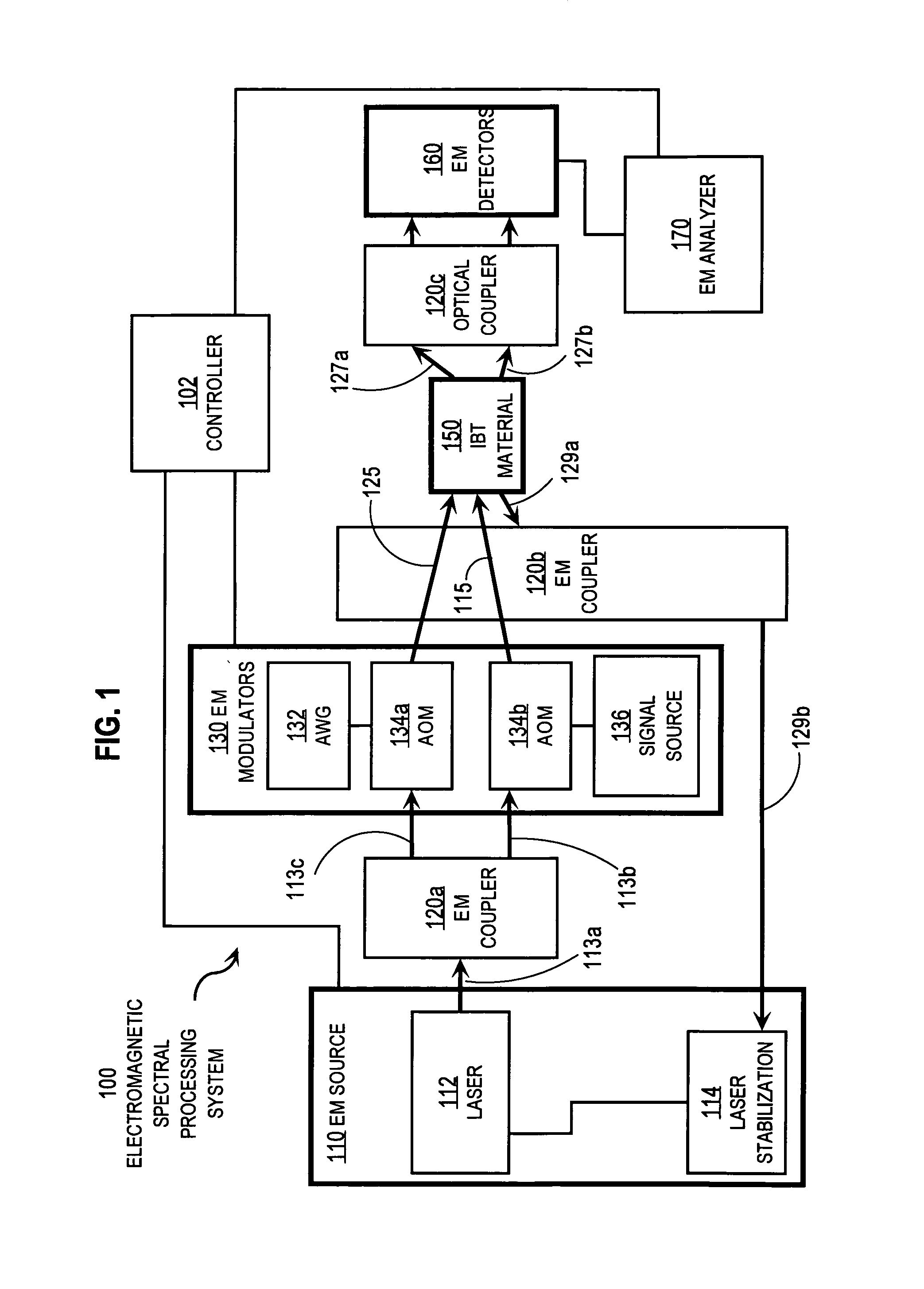
embodiment 100
[0057]In the illustrated embodiment 100, EM source 110 includes an input laser 112 and a laser stabilization block 114. This laser 112 provides stabilized optical carrier frequency beams 113a in the TeraHertz range (THz, 1 THz=1012 cycles per second) used to carry a target optical spectrum and a chirped laser field used as a probe waveform and a population reconfiguration waveform. In some embodiments, a single laser provides the carrier frequency beam 113a for both the target optical spectrum and probe signals. In some embodiments, additional laser sources are included in EM source 110. In some various embodiments, electric signals from laser stabilization block 114 controls frequency, amplitude or phase, or some combination, for laser 112. Propagation of EM waveforms is indicated in FIG. 1 by straight arrows. Electronic connections for signal processing and control are represented by segmented lines without arrowheads.
[0058]The EM couplers 120 direct EM waveforms, such as optical ...
embodiment 901
[0124]In embodiment 901 depicted in FIG. 9A, two sets of angled beams are used. One set programs the material by imposing spectral content while the other set erases spectral content in different spatial modes. Then the two sets switch, with the first set erasing in those spatial modes while the second set programs the different spatial modes. For example, at an initial time the first set of beams 920a and 920b interact to program the medium 910 with spectral contents in a first spatial mode. At a later time, when processing of that spectral content is completed, one or both of the first set of beams 920a and 920b send an erasure chirp into the medium 910 along the first spatial mode. Instead of waiting for the coherence time to reprogram the medium 910, the second set of beams 930a and 930b interact to program the medium 910 with new spectral content in a different second spatial mode. At successively later times, the first set 920a, 920b and the second set 930a, 930b, alternate in...
PUM
 Abstract
Description
Claims
Application Information