
Head mounted device

a head mounted display and display technology, applied in the field of head mounted displays, can solve problems such as the failure of conventional head mounted displays to gain popularity

Active Publication Date: 2007-12-11
HIMAX TECH LTD
View PDF2 Cites 26 Cited by
  • Summary
  • Abstract
  • Description
  • Claims
  • Application Information

AI Technical Summary

Problems solved by technology

The conventional head mounted display fails to gain popularity due to its large volume, heavy weight, and expensive price.

Method used


Image

  • Head mounted device
  • Head mounted device
  • Head mounted device

Examples


Embodiment Construction

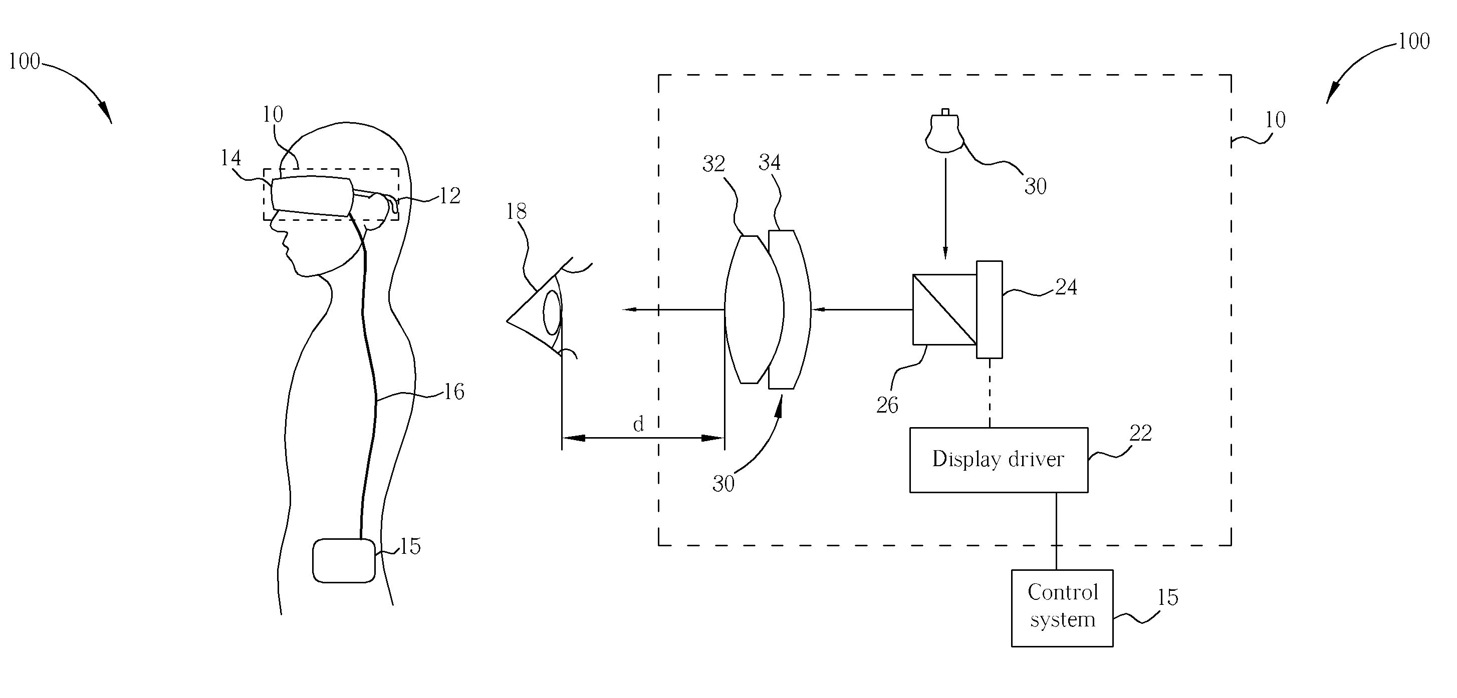
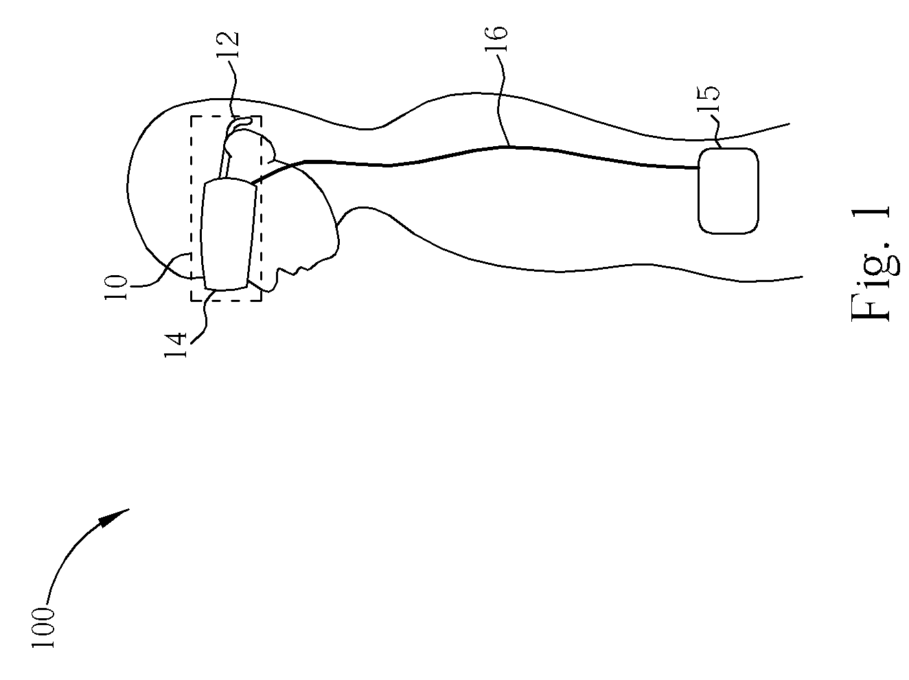
[0014]Please refer to FIG. 1, which shows an optical display system 100 having a head-mounted display 10 and a control system 15 according to the present invention. The user wears the head-mounted display 10 and can see vivid images through the display device 14 affixed to the frame 12 in response to the control system 15. The control system 15 is wirelessly connected or is wired-connected with the head-mounted display 10 by means of a transmission line 16.

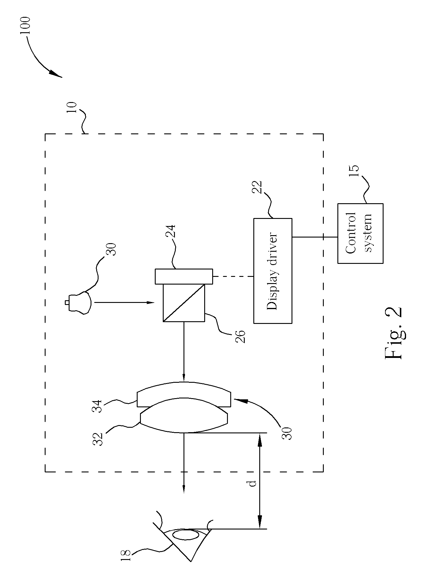
[0015]Please refer to FIG. 2, which shows a block diagram of the head mounted display 10. The display device 14 contains a lamp 20, a display driver 22, a liquid crystal on silicon (LCOS) panel 24, a polarization beam splitter (PBS) 26, and a lens group 30. Light emitted from the lamp 20 travels through the polarization beam splitter (PBS) 26 and reflects the S-type polarization light to the LCOS panel 24. The LCOS panel 24 modulates the received S-type polarization light into P-type polarization light based on a control signal fr...


PUM


Abstract

A head-mounted display (HMD) comprises a frame for hanging on a user's head, and a display device affixed to the frame. The display device comprises alight source, a driving circuit for generating data signals, a polarization beam splitter (PBS), for passing the light emitted from the light source, a liquid crystal on silicon panel (LCOS panel) for reflecting the light from the PBS based on the data signal generated by the driving circuit, and a lens group including a biconvex glass spherical prism and an aspherical plastic prism. The lens group is used for focusing the reflected light from the LCOS panel.

Description

BACKGROUND OF INVENTION[0001]1. Field of the Invention[0002]The present invention relates to a head mounted device, and more particularly, to a head mounted device utilizing an LCD panel.[0003]2. Description of the Prior Art[0004]A head-mounted display (HMD), a three-dimensional visual optical device, is the first device providing its wearer with an immersive experience. The typical HMD houses two miniature display screens and an optical system that channels the images from the screens to the eyes, thereby presenting a stereo view of a virtual world. Recently, the head mounted display as an input apparatus in response to a user's action is widely utilized in an augmented reality or a virtual reality system. Continuously measuring the position and orientation of the user's head by means of a motion tracker allows an image generating computer to adjust a scene representation to a current view. As a result, the viewer can look around and walk through the surrounding virtual environment...

Claims


Application Information

Patent Timeline
Patent Type & Authority Patents(United States)
IPC IPC(8): G02B27/14
CPCG02B27/0172G02B5/30G02B2027/0178
Inventor LI, KUO-YUINLIN, CHIA-FEN
Owner HIMAX TECH LTD
Learn More