Underbalanced drilling method and apparatus

a drilling method and a technology for subterranean wells, applied in the direction of drilling pipes, drilling rods, borehole/well accessories, etc., can solve the problems of preventing overbalanced drilling, reducing the efficiency of drilling, and reducing the cost of lost circulation, so as to simplify the flow composition of wellheads and reduce volume and footprint, the effect of substantially stable wellhead flow ra

Inactive Publication Date: 2007-12-18
STRAZHGORODSKIY SEMEN IOSIPHOVICH
View PDF3 Cites 37 Cited by
  • Summary
  • Abstract
  • Description
  • Claims
  • Application Information

AI Technical Summary

Benefits of technology

[0032](a) By flushing a well bore with a formation fluid being produced, conditions are created for drilling under balanced through a moderate to highly permeable formations, and loss circulation problem is eliminated.
[0034](c) By keeping wellhead flow rates substantially stable while drilling and making drill string connections as well as simplifying wellhead flow composition, conditions are created for using separating equipment of less volume and footprint.
[0035](d) By continuing to flush the well bore while making drill string connections the connection time may be dramatically decreased.

Problems solved by technology

In this overbalanced situation, materials are added to the drilling fluid to restrict fluid flow into formation by depositing low permeability filter cake on the borehole wall.
Overbalanced drilling prevents formation fluid blowouts.
But in certain conditions the drilling fluid flows into permeable formation and circulation may be partially or completely lost.
Lost circulation is a costly problem.
The production formation may be damaged by invading drilling fluid.
But drilling long vertical intervals or horizontal sections in highly permeable formations, especially with cavities and fractures, remains a serious problem.
Partial and full lost circulation is often encountered in such conditions.
If operator is not ready to treat and utilize the produced oil, UBD can't be implemented.
Water disposal may easily become a costly or prohibitive problem.
In UBD operations the well bore returns tend to be unstable in composition, pressure and rate.
The more productive is a formation the more unstable is the wellhead flow as a very small change in the drilling fluid circulating pressure leads to dramatic changes in formation fluid influx rate.
It is difficult and costly to handle the unstable wellhead stream, especially if formation fluid is natural gas.
Many problems in UBD techniques arise in periods of pump off for making connections.
The downhole pressure during resuming circulation usually exceeds the formation pressure allowing some volume of drilling fluid to enter the formation and damage it.
Prolific liquid producers can kill themselves during times of pump off and often circulation cannot be reestablished.
Connections in UBD operations usually take substantially more time in comparison with overbalanced drilling because some additional procedures are required, such as bleeding off, at least partially, the drill string, and repressurizing it thereafter.
It cannot be used reliably with a system evacuating drill cuttings to the surface through the drill string, as it takes place in reverse circulation, because cuttings may damage thread of the box.
The least erosion of the threaded end of the drill pipe joint may result in severe complications due to washouts.
It means that resources invested in UBD drilling of more than 6,000 wells were substantially lost.

Method used


Image

  • Underbalanced drilling method and apparatus
  • Underbalanced drilling method and apparatus
  • Underbalanced drilling method and apparatus

Examples


first embodiment

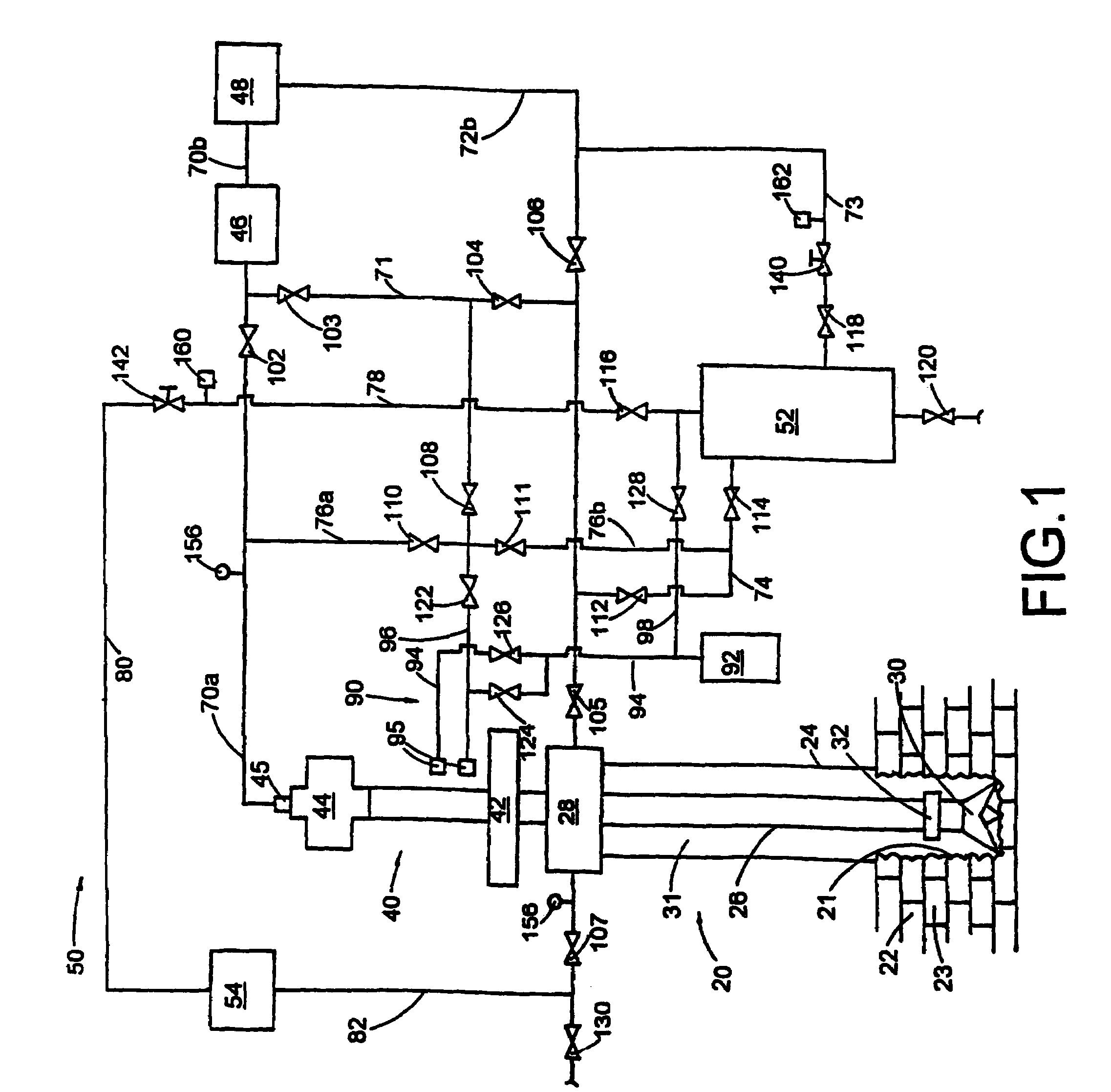
[0052]Referring to the FIG. 1, there is depicted a drilling rig 40 and an outlay of component parts of an above the ground system 50 which may be included with the drilling rig to practice an under balanced drilling method of this invention. A well bore 20 is drilled through the permeable formation 22, and a formation fluid 23 is gas. A casing 24 is placed above formation 22. The well bore has an open hole section 21. A drill string 26 comprises a series of interconnected joints of drill pipe with a through bore. A blow out preventer stack comprises a rotating blowout preventer (RBOP) 28. A drill bit 30 is attached to the drill string. The drill string may comprise a Measurement While Drilling (MWD) device 32 which is capable to provide information comprising the bottom hole pressure.

[0053]Drilling rig 40 may comprise a rotary table 42. A top drive 44 may be provided for rotating the drill string. The drilling rig may comprise a mud pump 46 and a drilling fluids handling facility 48...

second embodiment

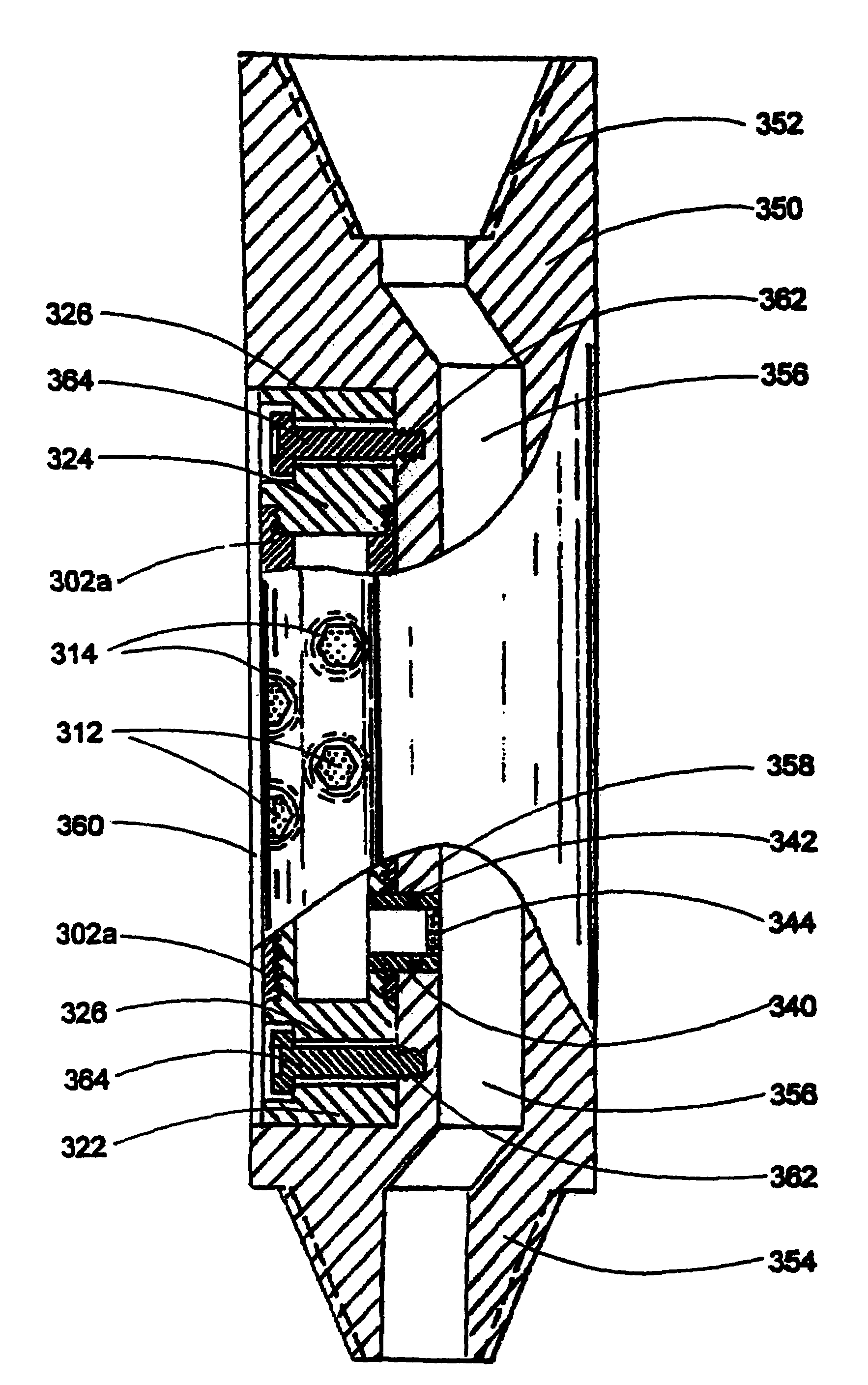
[0145]FIGS. 9 and 10 show the of the adjustable lifting gas injector (LGI). In this embodiment LGI comprises a flow regulator 320 and a side pocket sub 350.

[0146]Referring to the FIG. 9, flow regulator 320 comprises a tubular member 302a with at least one of a plurality of openings 310. The openings are adopted to include a porous insert 312 or a plug of the same shape (not shown). Inserts and plugs may be kept in place by a threaded retainer 314. Openings 310 with porous inserts and plugs constitute an inlet port of LGI. A check valve 330 is mounted inside the tubular member and is kept in place with a threaded lower plug 322. Lower plug 322 and an upper plug 324 seal the tubular member which is thereafter referred to as a housing 302a of the flow regulator. Each plug may comprise a bore 326 for placing a bolt (not shown in FIG. 8).

[0147]A connecting pipe 340 is mounted into a side opening 341 of housing 302a below the check valve.

[0148]A check valve 330 may comprise a housing 332 ...

third embodiment

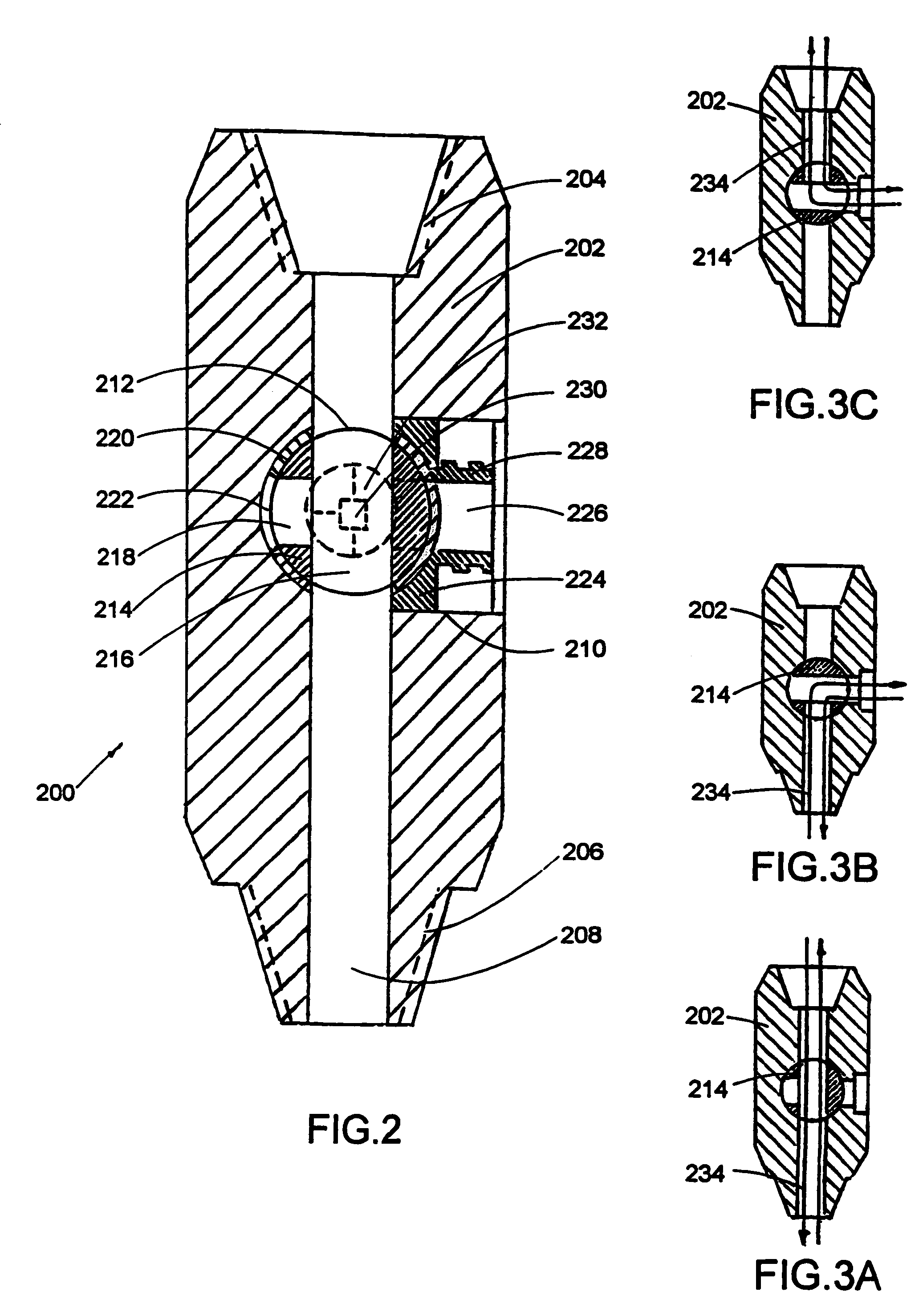
[0154]FIG. 11 depicts a remotely controlled flow regulator 400 which is adopted to be mounted in the side pocket of the sub as it has been described above for flow regulator 320 with reference to FIG. 10. Flow regulator 400 together with the side pocket sub described above constitutes the lifting gas injector of the invention.

[0155]Remotely controlled flow regulator 400 comprises a housing 402, a check valve 330, a connecting pipe 340, plugs 322, 324, a piston 406, a power unit 410, a bearing 412.

[0156]The housing may comprise a plurality of side openings 310. The openings are adopted to include a porous insert 312. Inserts may be kept in place by a threaded retainer 314. Side openings with porous inserts constitute the inlet port of the flow regulator. The way of choosing the number and area of side openings as well as choosing permeability coefficient of inserts is the same as it was disclosed above with reference to FIG. 8

[0157]A check valve 330 may comprise a housing 332 with an...


PUM


Abstract

A method of drilling well bore (20) through and below permeable formation (22) bearing such fluids as gas, oil, water wherein drill cuttings may be evacuated by formation fluid (23) being produced through the drill string (26) either by decreasing well head back pressure or by gas lift. Production rate is kept substantially stable by operating choke valves (140) and (142) placed after separator (52). Formation fluid being produced while drilling may be pumped into well bore (20) through annulus (31) or utilized. The unique injector included in the drill string provides for possibility to pump simultaneously into annulus (31) lifting gas and produced liquid and may be operated from the surface. A method and system (90) comprising a plurality of special 3-way valves included in drill string (26), are provided for making connections without interrupting flushing the well bore.

Description

CROSS REFERENCES TO RELATED APPLICATIONS[0001]Not ApplicableFEDERALLY SPONSORED RESEARCH AND DEVELOPMENT[0002]Not ApplicableBACKGROUND OF THE INVENTION[0003]1. Field of the Invention[0004]The present invention relates to drilling subterranean well bores, specifically to improved under balanced method and apparatus for drilling a well bore through or below a permeable formation containing such fluids as oil, gas, and water.[0005]2. Description of the Related Art[0006]Drilling a well bore typically requires circulating a drilling fluid to flush the bore of cuttings produced by action of a drill bit. The drilling fluid may be pumped down the well inside the drill string and, with picked up cuttings, back to the surface through the annulus outside the drill string. In another form, known in the art as reverse circulation, the drilling fluid is pumped through sealed annulus between a casing and the drill string, and drill cuttings are evacuated through the drill string.[0007]Traditional ...

Claims


Application Information

Patent Timeline
Patent Type & Authority Patents(United States)
IPC IPC(8): E21B43/00E21B7/00E21B21/00E21B21/10E21B21/14E21B21/16
CPCE21B21/00E21B21/103E21B21/16E21B21/14E21B2021/006E21B21/085E21B21/019E21B21/065
Inventor STRAZHGORODSKIY, SEMEN IOSIPHOVICH
Owner STRAZHGORODSKIY SEMEN IOSIPHOVICH
Why Eureka
Try Eureka