Autostereoscopic projection device and display apparatus

a projection device and display device technology, applied in the field of optical devices, can solve the problems of increasing the complexity of the optical path design of the projection apparatus, not only complicating the control, but also the compactness of the projection device, and achieves the effects of simple control mechanism, improved conversion efficiency, and simplified optical path design

Inactive Publication Date: 2015-05-14
DELTA ELECTRONICS INC
View PDF9 Cites 14 Cited by
  • Summary
  • Abstract
  • Description
  • Claims
  • Application Information

AI Technical Summary

Benefits of technology

[0009]In view of the foregoing subject, an objective of the invention is to provide an autostereoscopic projection device which has simpler optical path design, simpler control mechanism, better conversion efficiency, and less volume and weight.

Problems solved by technology

However, this kind of design causes a considerable difficulty to the compactness of the projection device, and the optical path design among the projection apparatuses will become more complicated.
Accordingly, this design of using the switch elements not only complicates the control but also reduces the total imaging efficiency.

Method used


Image

  • Autostereoscopic projection device and display apparatus
  • Autostereoscopic projection device and display apparatus
  • Autostereoscopic projection device and display apparatus

Examples


first embodiment

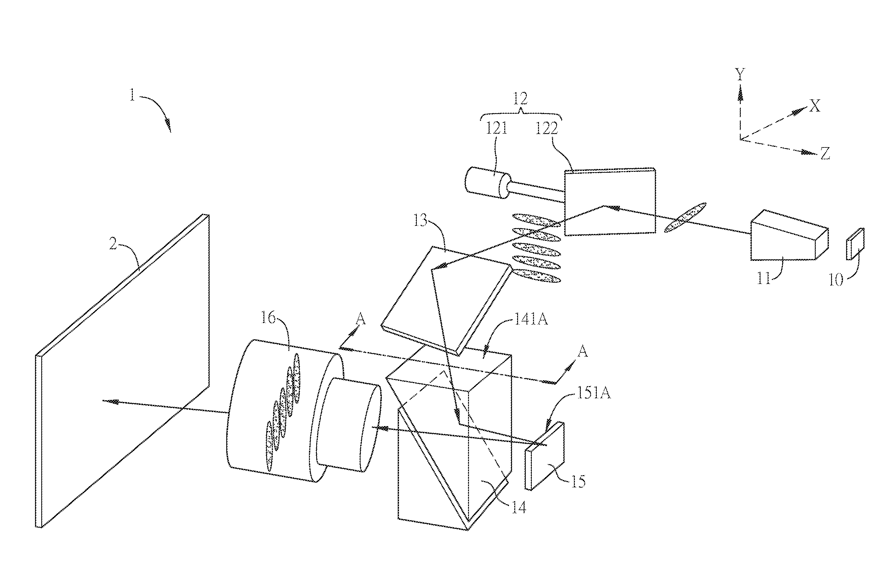
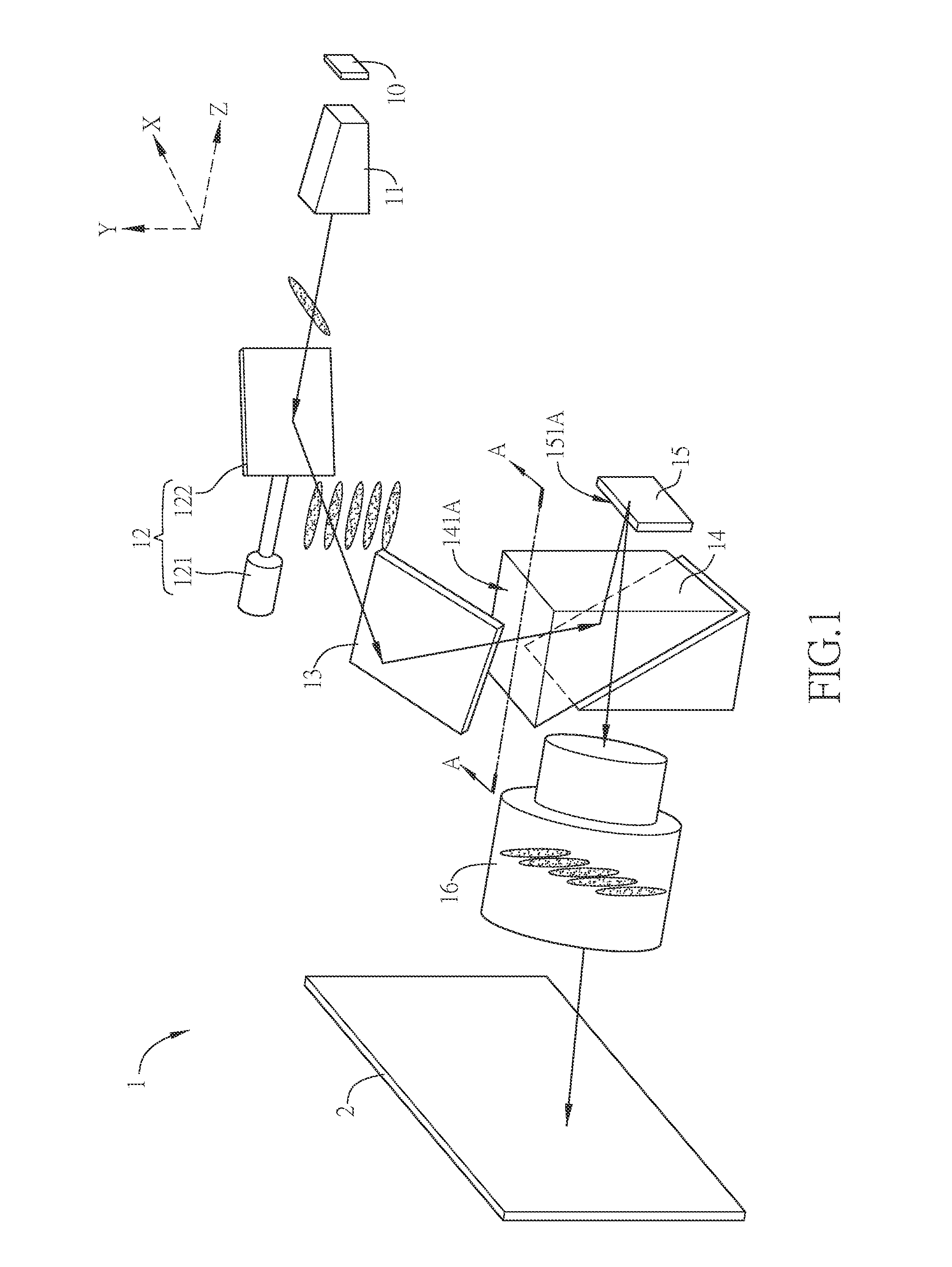
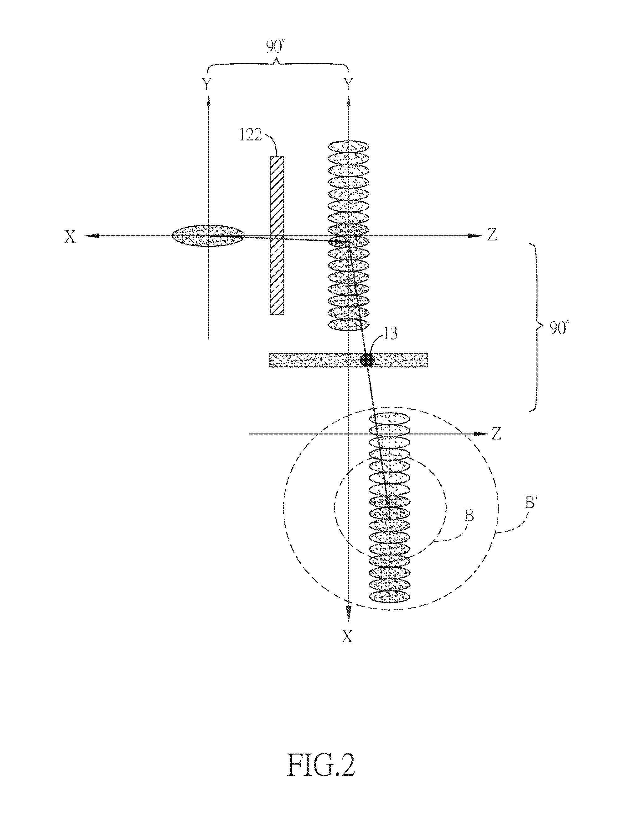
[0043]FIG. 1 is a schematic diagram of an autostereoscopic projection device according to the invention, FIG. 2 is a schematic diagram of the imaging of the autostereoscopic projection device in FIG. 1, FIGS. 3 and 5 are other schematic diagrams of the imaging of the autostereoscopic projection device in FIG. 1, and FIG. 4 is a schematic sectional diagram taken along the line A-A in FIG. 1.

[0044]The projection device 1 of this embodiment at least includes a light source module 10, a light scanning module 12, a light transmitting module 13, a light combining module 14, a spatial light modulator module 15 and a lens 16. The light emitted by the light source module 10 is transmitted through the light scanning module 12, the light transmitting module 13, the light combining module 14 and the spatial light modulator module 15 sequentially, and then leaves the projection device 1 through the lens 16.

[0045]The light source module 10 is disposed on a side of the light scanning module 12 and...

second embodiment

[0064]FIG. 7A is a schematic diagram of an autostereoscopic projection device according to the invention, and FIG. 7B is a schematic side view of the autostereoscopic projection device in FIG. 7A.

[0065]Different from the 1-chip projection device of the first embodiment (FIG. 1), the projection device of this embodiment is a 3-chip digital optical processing device.

[0066]In this embodiment, in addition to the first light combining element 141, the light combining module 14 can further include a second light combining element 142, which can be a total reflection prism for example.

[0067]Besides, in addition to the first spatial light modulator element 151, the spatial light modulator module 15 can further include a second spatial light modulator element 152 and a third spatial light modulator element 153, both of which can be a digital micromirror device (DMD).

[0068]The light emitted by the light source module 10 is transmitted through the light scanning module 12, the light transmitti...


PUM


Abstract

An autostereoscopic projection device comprises a light source providing a light, a light scanning module, a light transmitting module, a light combining module including a first light combining element, a spatial light modulator module including a first spatial light modulator element, and a lens. The light scanning module includes a reflective surface and an actuating device capable of deflecting the reflective surface. The normal vector of an incident surface of the first light combining element is coplanar with the normal vector of a reflective surface of the first spatial light modulator element, and the coplanar plane is perpendicular to a disposition plane of the projection device. The light provided by the light source module is transmitted through the light scanning module, the light transmitting module, the light combining module and the spatial light modulator module sequentially and then leaves the projection device through the lens.

Description

CROSS REFERENCE TO RELATED APPLICATIONS[0001]This Non-provisional application claims priority under 35 U.S.C. §119(a) on Patent Application No(s). 102140972 filed in Taiwan, Republic of China on Nov. 12, 2013, the entire contents of which are hereby incorporated by reference.BACKGROUND OF THE INVENTION[0002]1. Field of Invention[0003]The invention relates to an optical device and, in particular, to an autostereoscopic projection device.[0004]2. Related Art[0005]Recently, with the progress of the stereoscopic display technology, many stereoscopic products, such as stereoscopic movies and stereoscopic TVs, are produced for various commercial applications. The basic concept of the stereoscopic display technology is to transmit the left-eye images and the right-eye images with different viewing angles to the left eye and right eye of the viewer respectively, and both of these 2D images are then combined in the viewer's brain to give the perception of 3D depth while the viewer perceive t...

Claims


Application Information

Patent Timeline
Patent Type & Authority Applications(United States)
IPC IPC(8): G02B27/22G02B30/29
CPCG02B27/225G02B30/29G03B21/28G03B21/208G03B21/2033G02B30/27
Inventor HUANG, JUNE-JEI
Owner DELTA ELECTRONICS INC
Why Eureka
Try Eureka