Optical isolator and optical device

a technology of optical isolators and optical devices, which is applied in the direction of optics, polarising elements, instruments, etc., can solve the problems of the dimension of the optical isolator in the direction along the optical path is large, and the difficulty in reducing the size of the amplifier, so as to reduce the number of optical elements used for forming the optical isolator, the manufacturing process and the manufacturing cost of the optical isolator can b

Inactive Publication Date: 2007-08-02
NAMIKI PRECISION JEWEL CO LTD
View PDF3 Cites 8 Cited by
  • Summary
  • Abstract
  • Description
  • Claims
  • Application Information

AI Technical Summary

Benefits of technology

[0039] According to the optical isolator of the invention, it is possible to limit the kinds of optical devices which constitute the optical isolator only to a birefringent element; a Faraday rotator; and a lens and a total reflection member. Thus, the optical elements such as a half-wave plate and a glass plate which have been necessary for conventional optical isolators having going-returning optical paths can be eliminated. Consequently, an optical isolator structure having optical going paths can be achieved, wherein the kinds and the number of the optical elements used for constituting the optical isolator are decreased, as a result of which the manufacturing process and manufacturing cost thereof can be reduced.
[0040] Further, the optical isolator according to the present invention is constituted only by optical elements indispensable for providing the optical isolator function, so that the optical path design is simplified and the structure of the optical isolator can be simplified and reduced in size and cost. Furthermore, since one of the first and second birefringent elements, which are indispensable optical elements for providing the optical isolator function, is imparted with the PDL and PMD reduction function, it is also possible to further enhance the property of the optical isolator.
[0041] For the optical isolators having going-returning optical paths using reflection, light is transmitted through the same optical element twice, so that the PMD and PDL which occur in the single optical element are doubled and affected to the light outgoing from the optical isolator. In contrast, for the optical isolator of the invention, the PMD and PDL which occur in the going optical path are reduced before the light is reflected by the total reflection member, so that it can be prevented that the returning optical path is severely affected by the PMD and PDL. Further, the PMD and PDL which occur in the returning optical path are also reduced by transmitting the light through the first birefringent element or second birefringent element, which is subjected to correction of the crystal axis orientation and correction of the thickness in the direction of the normal to the element. For this reason, it becomes possible to reduce the PMD and PDL of the propagating light can be reduced to a desired numeral level until the propagating light is caused to enter the optical fiber on the light incident side.
[0042] In addition, when the PDL and PMD reduction function is imparted to the first or second birefringent element, a preference for correcting the PDL or for correcting PMD can be determined only by changing the crystal axis angle and the thickness in the element surface normal direction of the element of any one of the first and second birefringent elements. Thus, the aforementioned preference can be easily changed depending on the application and required features of the respective optical isolators so that application of the optical isolators can be expanded without difficulty.
[0043] When priority is given to the correction to minimize a isolated width which directly influences the PDL effect of the optical isolator, the light rays of the two paths can be completely reflected at a substantially single point on the total reflection member. Thus, the difference in optical path length between the two optical paths within the lens associated with the total reflection can be substantially eliminated. Accordingly, the PDL which occurs between the light rays of the two optical paths, i.e., the going-returning optical paths, within the lens can be reduced to a desired numeral level.
[0044] Further, in the forward direction optical path, the crystal axis orientations of the first and second birefringent elements and the thicknesses of the first and second birefringent elements in the element surface normal direction are set such that the center positions of the respective polarization planes of the ordinary ray and extraordinary ray after transmitting through the first and second birefringent elements are equi-spaced from a single point on the total reflection member. Therefore, the optical path lengths of the ordinary and extraordinary rays to the single point within the lens can be made equal. Thus, it is possible to substantially eliminate the difference in optical path length between the ordinary ray and the extraordinary ray within the lens associated with the total reflection by the total reflection member, which provides better effect in reducing the PDL.

Problems solved by technology

For this reason, when the amplifier receives optical feedback reflected from the optical elements or from the light inlet / outlet end of the optical fiber inside the amplifier, the light resonates, which results in degradation of the amplification.
In such an arrangement, however, since the respective optical elements are arranged in series, the dimension of the optical isolator in the direction along the optical path is large and cannot be reduced in size.
Therefore, when the aforementioned optical isolator is incorporated in an amplifier, a large area is required for routing the optical fibers within the amplifier because the optical fiber cannot be bent in a smaller radius due to the bending loss of the optical fiber, wherein the problem arises that reducing the size of the amplifier is difficult.
Thus, at least two lenses are necessary for each optical isolator, which results in the problem that the number of constituent components increases.
As a result, reduction in coupling efficiency between the propagating light and the optical fiber 102 is caused.
Therefore, they are not necessarily efficient means for reducing the manufacturing process and the manufacturing cost.
Thus, in terms of decreasing the absolute number of components, it is not a desirable structure.
Further, since the structure shown in FIG. 15 is devised to provide both the optical multiplexing function and the optical isolator function by a single optical device, its optical path design is made more complex.
Thus, the suggestion was not sufficient for simplification of the structure and reduction in the size and cost of the optical isolator incorporated in the amplifier.

Method used


Image

  • Optical isolator and optical device
  • Optical isolator and optical device
  • Optical isolator and optical device

Examples


first embodiment

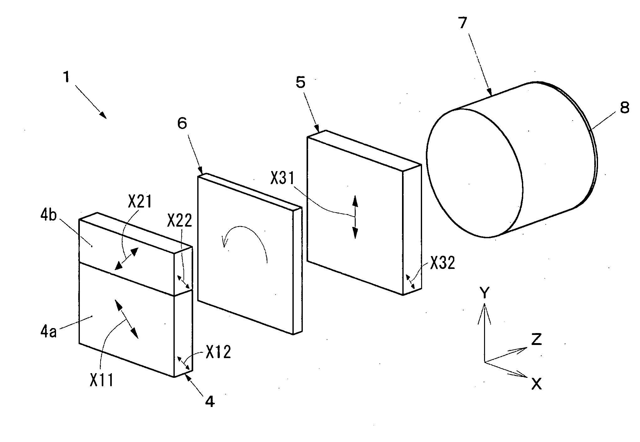
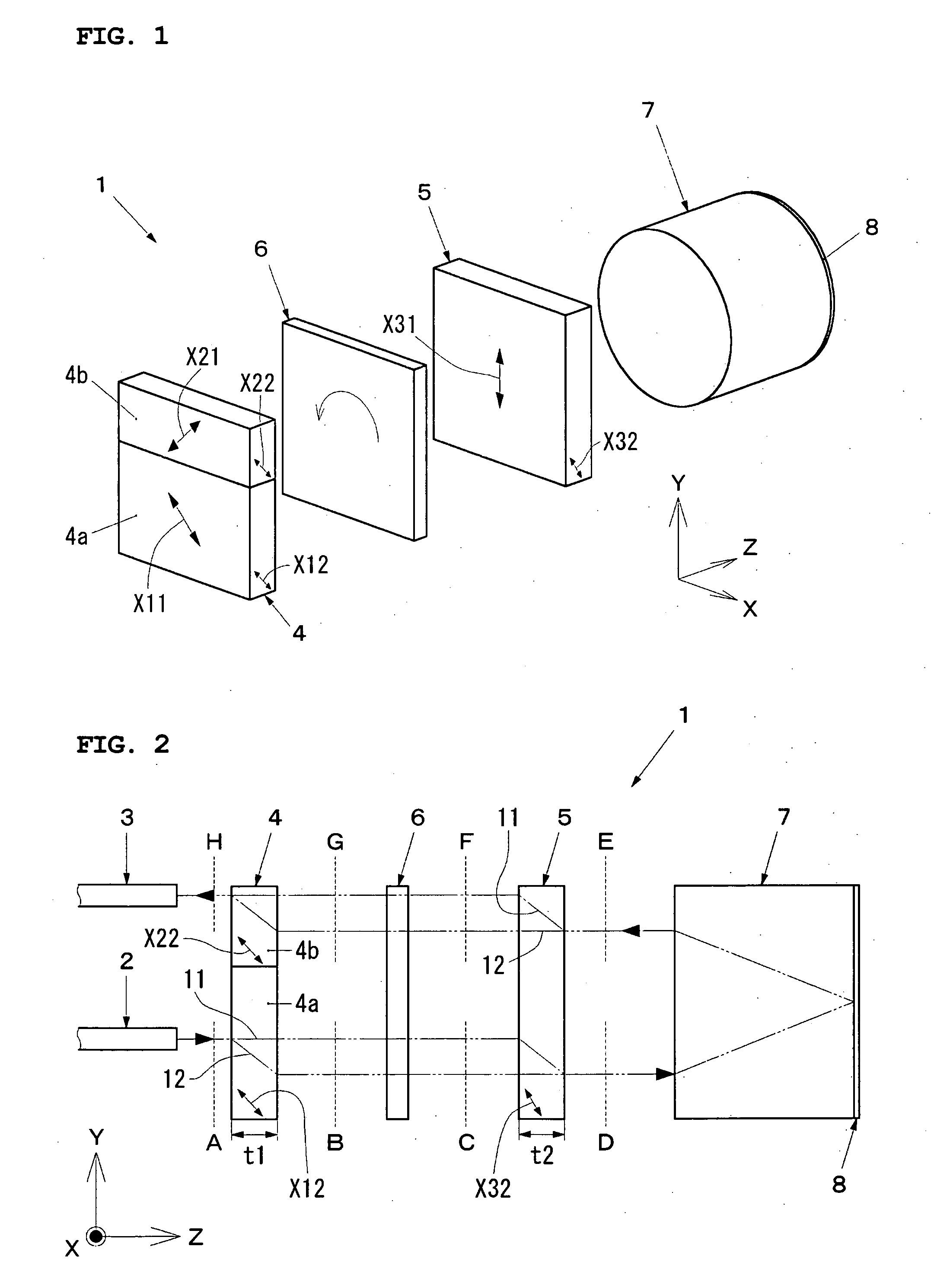
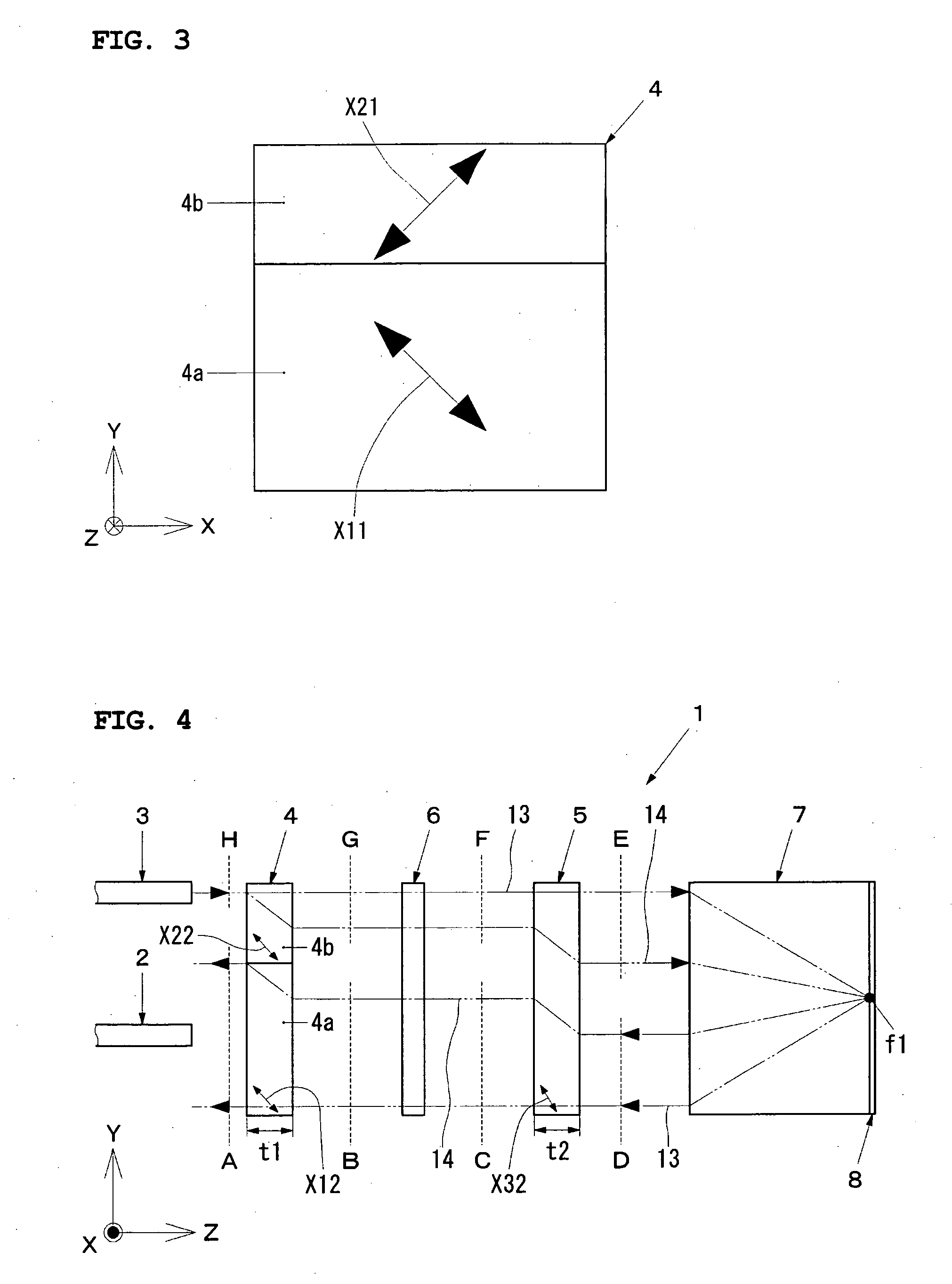
[0078] A first embodiment of the present invention will be described in detail below with reference to FIG. 1 to FIG. 6. FIG. 1 is a schematic perspective view showing an optical isolator according to a first embodiment of the invention; FIG. 2 is a side view of an optical device comprising the optical isolator in FIG. 1 and a plurality of optical fibers optically coupled to the optical isolator, showing optical paths when light propagates in the forward direction; FIG. 3 is a plan view of a first birefringent element which is a constituent component of the optical isolator in FIG. 1, viewed from the side facing the optical fibers; and FIG. 4 is a side view of the optical device, showing optical paths when light propagates in the reverse direction.

[0079] As shown in FIG. 1 to FIG. 4, an optical isolator 1 is constituted by a first birefringent element 4 (rutile type crystal), a second birefringent element 5 (rutile type crystal), a Faraday rotator 6, a magnet (not shown) for magnet...

second embodiment

[0161] A second embodiment of the present invention will be described in detail below with reference to FIG. 8 to FIG. 10. FIG. 8 is a schematic perspective view showing an optical isolator according to a second embodiment of the invention; FIG. 9 is a side view of an optical device comprising the optical isolator in FIG. 8 and a plurality of optical fibers optically coupled to the optical isolator, showing optical paths when light propagates in the forward direction; and FIG. 10 is a side view of the optical device, showing optical paths when light propagates in the reverse direction. Note that similar parts to those of the optical isolator 1 and the optical device described in the description of first embodiment are assigned the similar number, and descriptions thereof are omitted or simplified.

[0162] As shown in FIG. 8 to FIG. 10, an optical isolator 1′ is constituted by a first birefringent element 4 (rutile type crystal), a second birefringent element 5 (rutile type crystal), ...


PUM

PropertyMeasurementUnit
rotation angleaaaaaaaaaa
angleaaaaaaaaaa
angleaaaaaaaaaa

Abstract

A simple-structure, small-size, inexpensive optical isolator mounted in an amplifier. The PMD and PDL are reduced to desired numerical levels to improve the characteristics. The optical isolator is composed of two double refraction elements, a 45 DEG Faraday rotator, a magnet, a lens, and a total reflection member. The directions of crystal axes of the two double refraction elements and the direction of the rotation of the Faraday rotator are appropriately set. Therefore, going-returning optical paths where incident unpolarized light is separated into ordinary light and extraordinary light, totally reflected by a total reflection member, and outputted are formed. The direction of the crystal axis with respect to the direction of the normal on the element surface of either of the two double refraction elements and the thickness in the direction of the normal on the element surface are corrected.

Description

TECHNICAL FIELD [0001] The present invention relates to a polarization-independent optical isolator, which is inserted (in an in-line arrangement) between optical fibers for optical communication equipment and optical information processors, and operates regardless of the plane of light polarization. The present invention also relates to an optical device provided with such an optical isolator. BACKGROUND ART [0002] When the amount of light is attenuated, for example, and propagates through an optical fiber for a long distance or when light branches from an optical fiber, the light is optically amplified by an erbium-doped optical fiber amplifier (hereinafter referred to as “amplifier”) or the like. This amplification amplifies light directly without converting the light to an electrical signal. The aforementioned amplifier is constituted by a lot of optical devices such as a lens, mirror, and filter and the like. For this reason, when the amplifier receives optical feedback reflect...

Claims


Application Information

Patent Timeline
Patent Type & Authority Applications(United States)
IPC IPC(8): G02B27/28G02B6/26G02F1/09
CPCG02F1/093G02B6/2746
Inventor KONNO, YOSHIHIROSASAKI, MASARU
Owner NAMIKI PRECISION JEWEL CO LTD
Why Eureka
Try Eureka