
Binocular eyepiece assembly and binocular telescope

Active Publication Date: 2018-02-01
LONGPERNG
View PDF3 Cites 2 Cited by
  • Summary
  • Abstract
  • Description
  • Claims
  • Application Information

AI Technical Summary

Benefits of technology

The present invention provides a lightweight binocular eyepiece assembly for a common telescope that has a simple optical path design. It can be matched with a single-tube objective tube and make observation more comfortable for the user. The assembly is designed with a complete and simple structure and optical path that can be miniaturized. The technical effects of this invention are to provide a comfortable and efficient observation platform for a single-tube telescope.

Problems solved by technology

Therefore, even though the binocular telescope is more complex and heavier than the monocular telescope, and has worse optical effects, the binocular telescope is still popular with most of people.
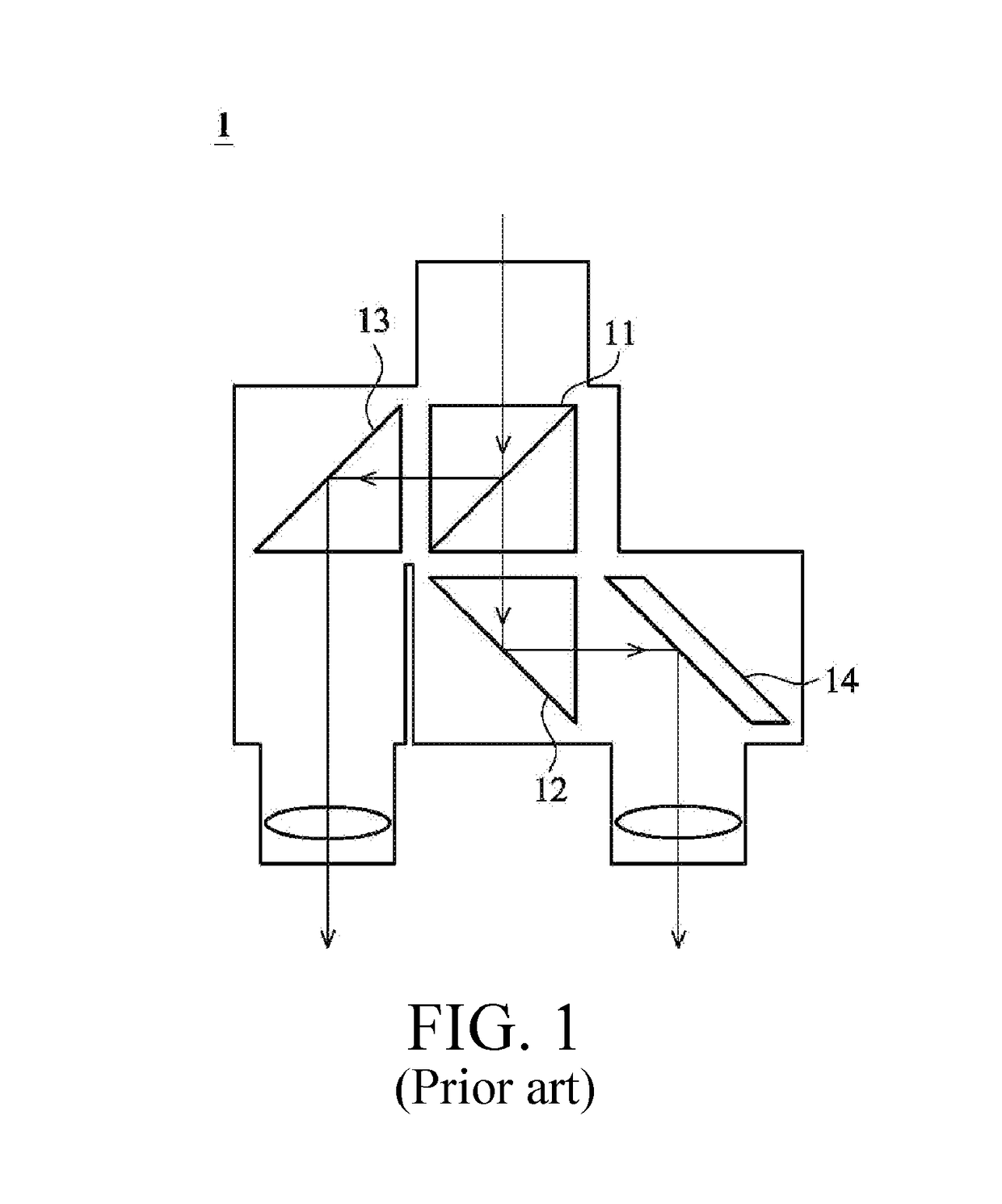
However, such an approach has at least the following disadvantages: First, a splitting ratio of the beam splitter is unfavorable, and splitting quality of the beam splitter depends on a coating technology.
Further, it is difficult to miniaturize the beam splitter, and therefore, the entire volume of the telescope cannot be miniaturized.
In addition, when a binocular telescope with such configuration is assembled, the position of the beam splitter needs to be corrected particularly, and if the position of the beam splitter deviates, the splitting ratio is affected, resulting in uncomfortable observation experience of the user.
Moreover, costs are higher if the beam splitter is used.

Method used


Image

  • Binocular eyepiece assembly and binocular telescope
  • Binocular eyepiece assembly and binocular telescope
  • Binocular eyepiece assembly and binocular telescope

Examples


Embodiment Construction

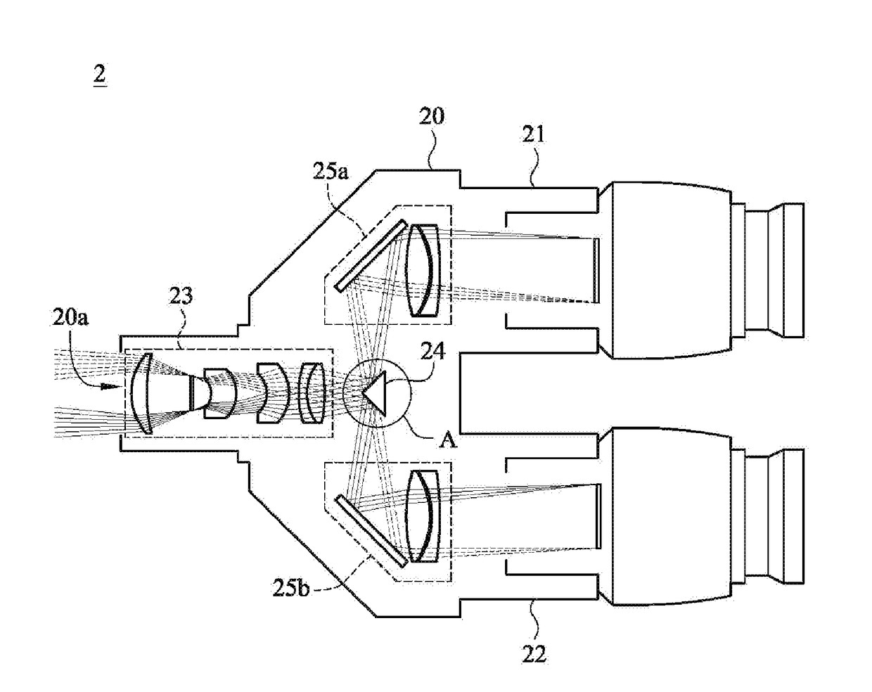
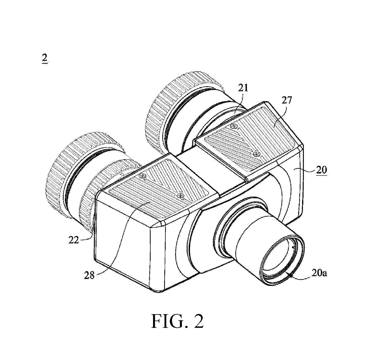
[0035]First, referring to FIG. 2 to FIG. 4, FIG. 2 is a schematic three-dimensional diagram of a single-tube binocular eyepiece assembly according to the present invention. FIG. 3A is a schematic diagram of an internal component and an optical path in FIG. 2. FIG. 3B is a schematic diagram of an optical path of an optical lens assembly in FIG. 3A. FIG. 4 is a schematic enlarged diagram of a beam splitting prism in FIG. 3A. Further, FIG. 4 is a schematic enlarged diagram of a frame A in FIG. 3A, and FIG. 3B is a schematic diagram of imaging when an exemplary optical lens assembly is used independently.

[0036]This embodiment is a single-tube binocular eyepiece assembly 2, which may be matched with a single-tube telescope for use. The single-tube telescope, for example, may be a terrestrial telescope or a portable observation telescope, but is not limited thereto.

[0037]The single-tube binocular eyepiece assembly 2 may include at least: a casing 20, an optical lens assembly 23, a beam sp...


PUM


Abstract

A binocular eyepiece assembly for telescope, the assembly includes a casing, an optical lenses assembly, a beam splitter, a first reflecting mirror unit and a second reflecting mirror unit. The casing has a left ocular portion, a right ocular portion and a light receiving portion. The optical lenses assembly, the beam splitter, the first reflecting mirror unit and the second reflecting mirror unit are disposed inside the casing, and furthermore, the beam splitter is disposed on the light axis of the light axis. The beam splitter has a first reflecting surface, a second reflecting surface and an included angle. The included angle is disposed between the first reflecting surface and the second reflecting surface. The included angle is a right angle. A light beam is received via the light receiving portion, and the light beam will be transmitted to the optical lenses assembly and a beam splitter.

Description

BACKGROUNDTechnical Field[0001]The present invention relates to a binocular eyepiece assembly, and in particular, to a single-tube binocular lens assembly for a single-tube telescope.Related Art[0002]Currently, telescopes may be roughly classified into monocular telescopes (single-tube) and binocular telescopes (dual-tube) in the market. The structure and optical design of a monocular telescope are relatively simple, and the monocular telescope is usually a single optical system constituted by an objective lens system and an eyepiece. In addition to also including an objective lens system and an eyepiece, a binocular telescope needs to split, by using a beam splitter, a beam into two optical systems for left and right eyes to use. Since ancient times, people are more accustomed to observing with both the left and right eyes. Therefore, even though the binocular telescope is more complex and heavier than the monocular telescope, and has worse optical effects, the binocular telescope ...

Claims


Application Information

Patent Timeline
IPC IPC(8): G02B23/04G02B7/12G02B25/00G02B23/18
CPCG02B23/04G02B25/001G02B7/12G02B23/18
Inventor CHIANG, CHUN-HSIEN
Owner LONGPERNG
Learn More