
Tendon-identifying, post tensioned concrete flat plate slab and method and apparatus for constructing same

a technology of post-tensioned concrete and flat-plate slabs, which is applied in the direction of bridges, bridge structural details, building repairs, etc., can solve the problems of less redundancy and robustness, and achieve the effect of optimizing efficient and cost-effective utilization

Active Publication Date: 2006-10-19
SARKKINEN DOUGLAS L
View PDF13 Cites 14 Cited by
  • Summary
  • Abstract
  • Description
  • Claims
  • Application Information

AI Technical Summary

Benefits of technology

"This patent describes a new type of concrete slab construction method and apparatus that uses post-tensioned flat plates and minimal amounts of concrete. The slab has a specific geometry with inwardly recessed surface areas that identify safe areas for drilling and boring. The method and apparatus allow for the efficient and cost-effective use of concrete in building construction while also incorporating the advantages of one-way and two-way slab systems. The resulting slab has a decreased mass and reduced seismic loading requirements, as well as lower post-tensioning and foundation and column structural requirements. The method also avoids the need for dedicated, permanent tendon-identifying marker apparatus. Overall, this invention provides a more efficient and cost-effective way to construct flat plate slabs while maintaining two-way structural behavior."

Problems solved by technology

Further, building codes also distinguish between one-way and two-way tensioned concrete slabs, applying more stringent requirements on one way slabs because of their lesser redundancy and robustness.

Method used


Image

  • Tendon-identifying, post tensioned concrete flat plate slab and method and apparatus for constructing same
  • Tendon-identifying, post tensioned concrete flat plate slab and method and apparatus for constructing same
  • Tendon-identifying, post tensioned concrete flat plate slab and method and apparatus for constructing same

Examples


Embodiment Construction

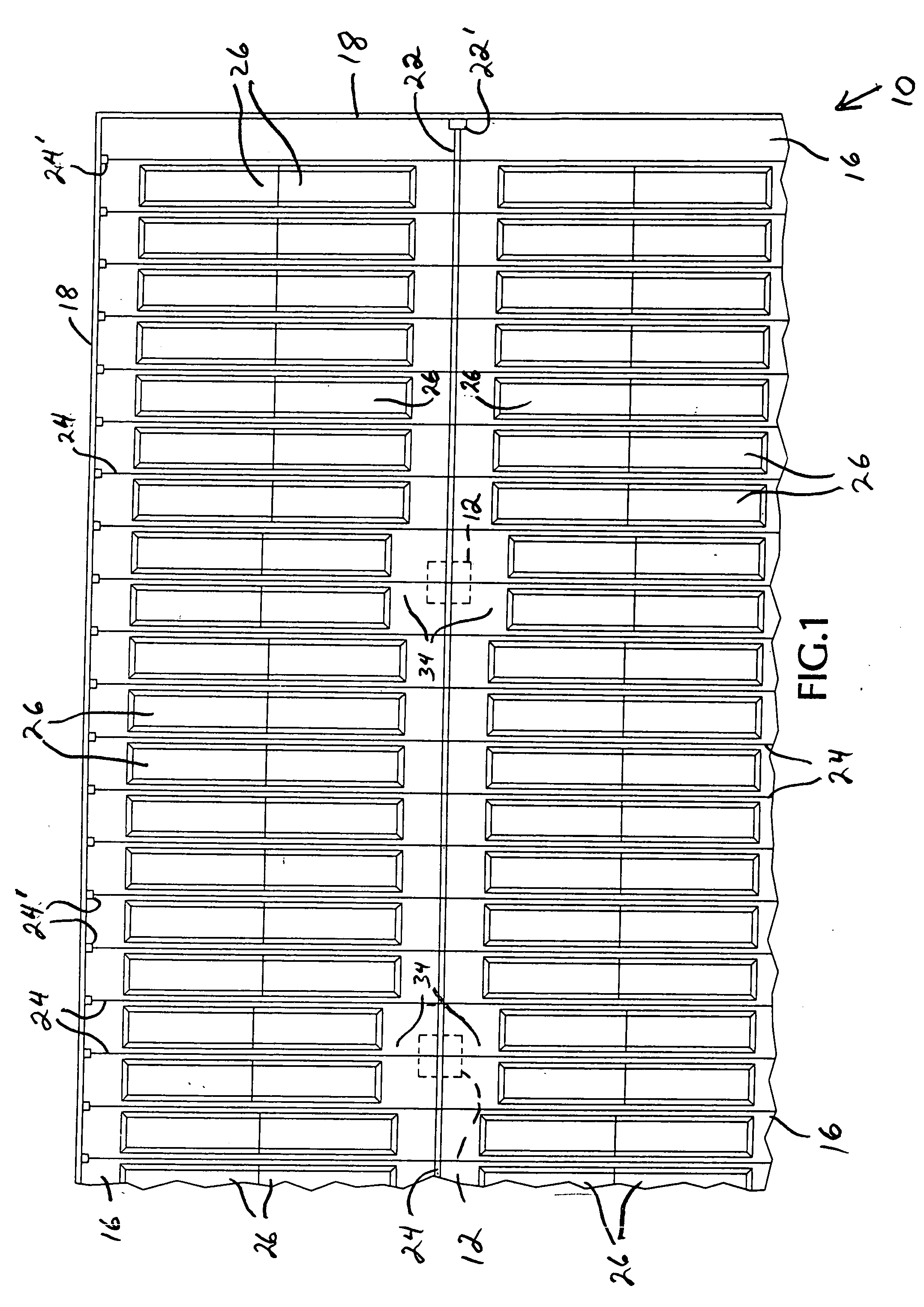
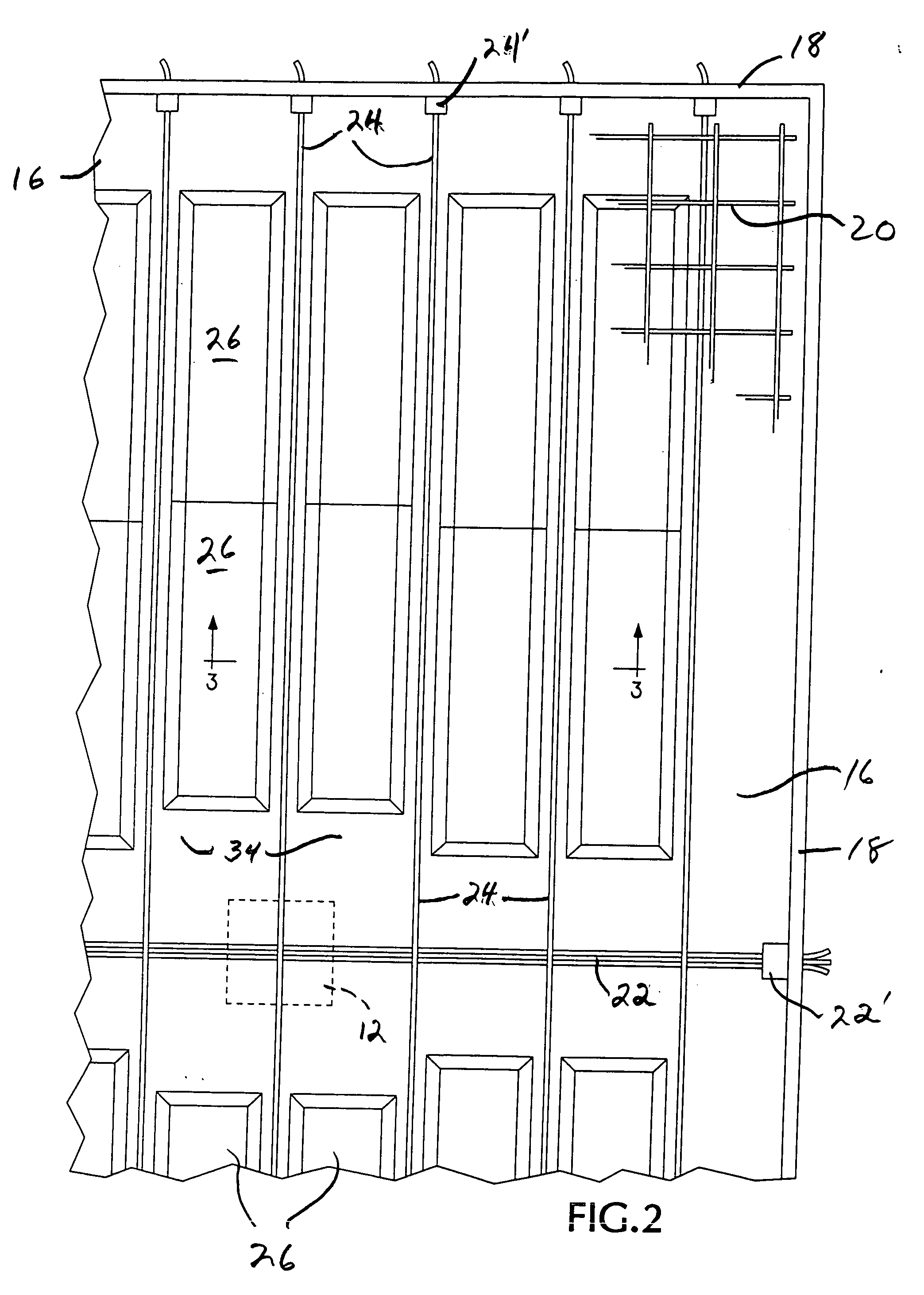
[0025]FIG. 1 is a fragmentary top plan view of a corner portion of a typical, temporary, elevated concrete flat plate type slab floor formwork structure 10 erected around the topmost portion of a plurality of previously-constructed, upstanding support columns 12 and supporting a plurality of form panel members to be described later. The upper ends of the columns are arranged for communication with the interior of the concrete slab formwork 10 as is well understood in the art.

[0026] As will be appreciated in viewing FIGS. 1 and 3 of the drawings, a temporary concrete flat plate slab formwork 10 typically provides an elevated, concrete-confining, support base structure having a plurality of floor joists 14 supported in an elevated condition by temporary upright posts (not shown). The floor joists in turn support a plurality of plywood sheets 16 which form a flat, temporary floor surface extending around the tops of the permanent columns 12 throughout the entire area of the future con...


PUM


Abstract

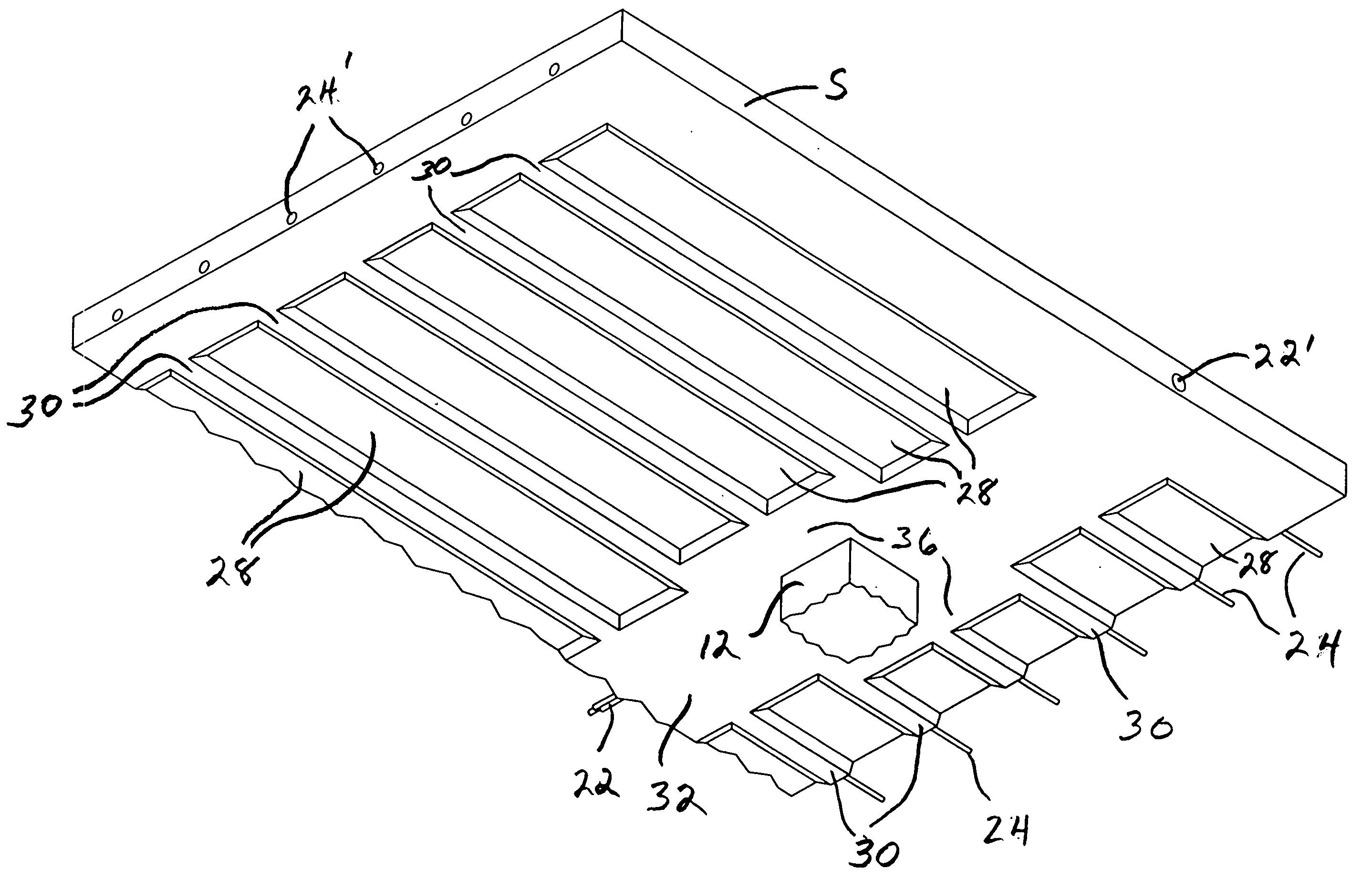
A tendon-identifying, post-tensioned, elevated concrete slab, and method and form panel apparatus for constructing the same, provides a distinctively-patterned bottom side slab surface in which the slab has a full thickness dimension extending along each individual post-tensioning uniform and banded tendon embedded within the slab and a reduced-thickness dimension in the areas between each individual, adjacent laterally spaced apart, longitudinally extending uniform tendon of the post-tensioning system, whereby the location of embedded tendons can be identified by the full thickness areas of the slab appearing as prominent, elongated rib-like surfaces extending between inwardly recessed surfaces of the bottom side of the slab.

Description

[0001] This application claims benefit under 35 U.S.C. 119(e) of the priority filing date of earlier filed U.S. Provisional application Ser. No. 60 / 666,371, filed 29 Mar. 2005.BACKGROUND OF THE INVENTION [0002] This invention relates to elevated concrete flat plate slab constructions, and more particularly to post-tensioned concrete concrete flat plate slab constructions which include a plurality of embedded, laterally spaced apart, tensioned uniform cable tendons extending in a first, longitudinal direction across the slab and a plurality of longitudinally spaced apart, tensioned banded cable tendons extending in a lateral direction over each row of support columns supporting the slab in elevated condition. In particular, the present invention provides a tendon-identifying post tensioned slab construction that effectively utilizes and combines the structural aspects of one-way slab type construction and two-way slab construction. These slab floor constructions are well known and ut...

Claims


Application Information

Patent Timeline
Patent Type & Authority Applications(United States)
IPC IPC(8): E04C5/08
CPCE01D19/125E01D2101/28E04G11/46E04B5/43E04C5/08E04B5/32
Inventor SARKKINEN, DOUGLAS L.
Owner SARKKINEN DOUGLAS L
Learn More