

Heatable vehicle glazing with antennas
- Summary
- Abstract
- Description
- Claims
- Application Information
AI Technical Summary
Benefits of technology
Problems solved by technology
Method used
Image

Examples
Embodiment Construction
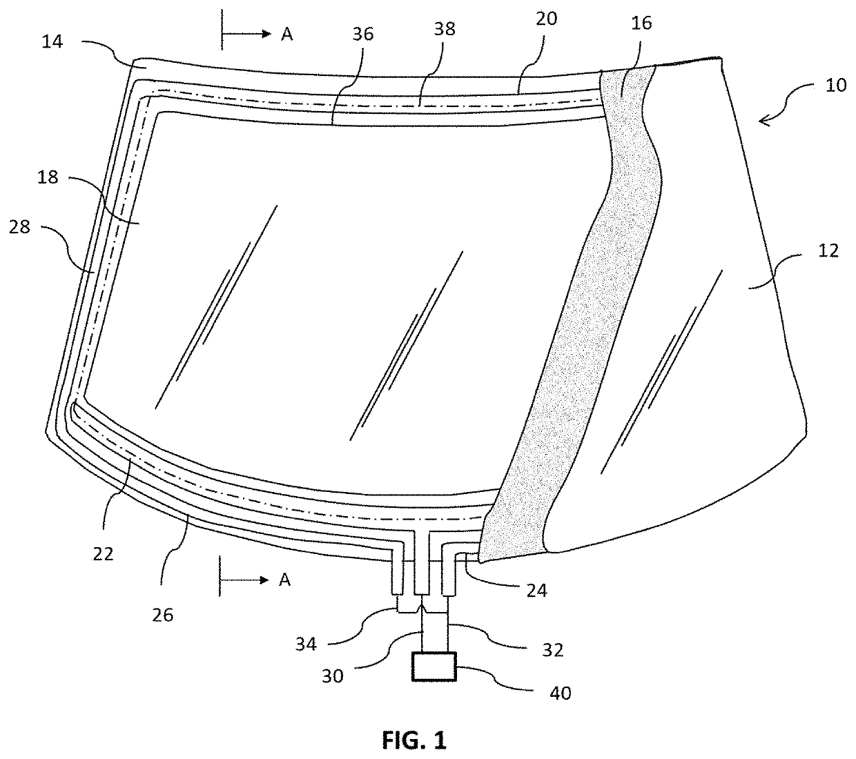
[0041]FIG. 1 shows a plan view of a transparent windshield 10 incorporating features of the presently disclosed invention. Window 10 is a laminated vehicle windshield formed of outer and inner glass plies 14 and 12 that are bonded together by an interposed layer 16, preferably of a polyvinyl butyral, polyvinyl chloride, polyurethane or similar material. Outer glass ply 14 defines an outer surface (conventionally referred to as the number 1 surface) on the outside of the vehicle and an inner surface (conventionally referred to as the number 2 surface). Inner glass ply 12 defines an outer surface (conventionally referred to as the number 3 surface) on the inside of the glazing and a surface (conventionally referred to as the number 4 surface) that faces toward the interior of the vehicle and is the internal side of window 10. Interlayer 16 is located between surface number 2 and surface number 3.
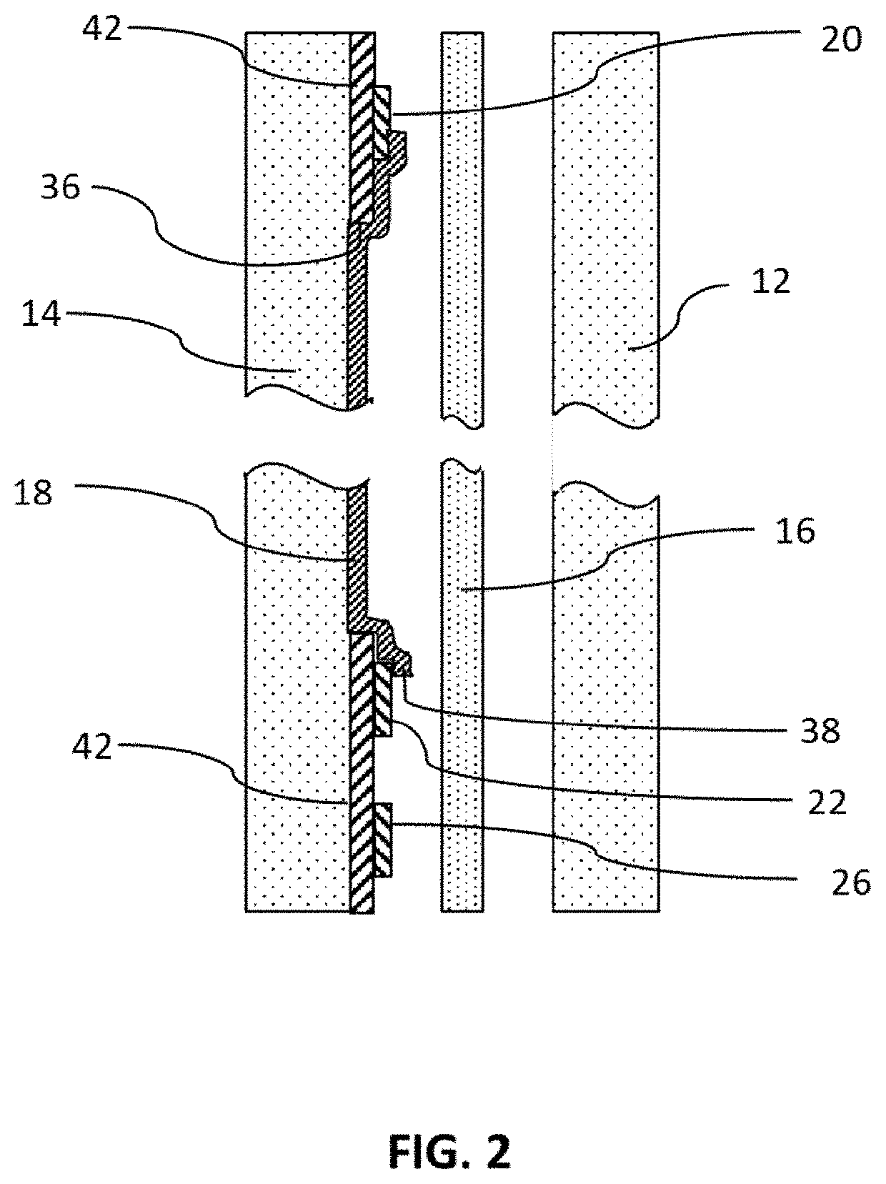
[0042]As shown in FIG. 2, the window glass 10 may include an obscuration band 42 formed by...
PUM
 Abstract
Description
Claims
Application Information